background image

4-18   Input / Output

MN1957

www.baldormotion.com

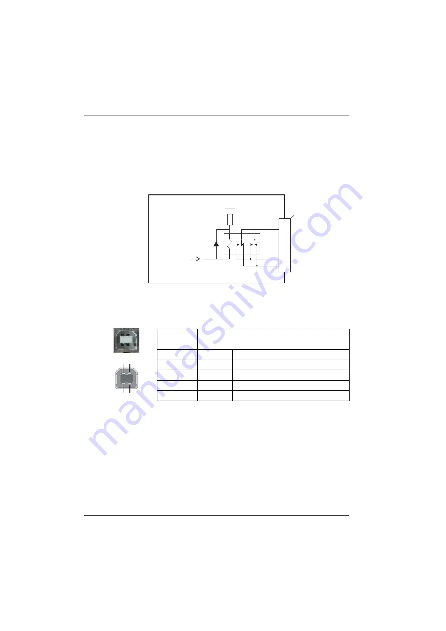
4.4.4 Relay connections

The relay connections are available on connector X12, as shown in section 4.1.1. The relay
outputs are isolated from any internal circuits in the NextMove ESB-2. In normal operation,
while there is no error, the relay is energized and REL COM is connected to REL NO. In the
event of an error or power loss, the relay is de-energized, and REL COM is connected to
REL NC.  The relay can be controlled by the 

RELAY

 keyword, and can be configured as the

global error output by setting 

GLOBALERROROUTPUT

 to 1000 (

_RELAY0

). See the Mint help

file. 

Figure 22: Relay connections

4.4.5 USB port

The USB connector can be used as an alternative method for connecting the
NextMove ESB-2 to a PC running Mint WorkBench. The NextMove ESB-2 is a self-powered,
USB 1.1 (12 Mbps) compatible device. If it is connected to a slower USB1.0 host PC or hub,
communication speed will be limited to the USB1.0 specification (1.5 Mbps).  If it is
connected to a faster USB2.0 (480 Mbps) host PC or hub, communication speed will remain
at the USB1.1 specification of the NextMove ESB-2.

Ideally, the NextMove ESB-2 should be connected directly to a USB port on the host PC. If it
is connected to a hub shared by other USB devices, communication could be affected by the
activity of the other devices.  A 2 m (6.5 ft) standard USB cable is supplied. The maximum
recommended cable length is 5 m (16.4 ft). 

Location

USB
Mating connector: USB Type B (downstream) plug

Pin Name

Description

1 VBUS

USB +5 V

2 D-

Data-

3 D+

Data+

4 GND

Ground

NextMove E

S

B-2

R

E

L COM

R

e

l

ay

R

E

L NC

R

E

L NO

X12

7

8

9

Mint

or

GLOBALERROROUTPUT

DRIVEENABLEOUTPUT

+

5

V

1

4

2

3

Servo Systems Co. • 115 Main Road • P.O. Box 97 • Montville, NJ, 

07045-0097 • (973) 335-1007 • Toll Free: (800) 922-1103  

Fax: (973) 335-1661 • www.servosystems.com

Summary of Contents for NextMove ESB-2

Page 1: ...MN1957 NextMove ESB 2 Servo Systems Co 53 Green Pond Road Suite 2 Rockaway NJ 07866 Fax 973 335 1661 www servosystems com...

Page 2: ...al I O 4 7 4 3 1 Digital inputs 4 7 4 3 2 Digital outputs 4 12 4 4 Other I O 4 13 4 4 1 Stepper control outputs models NSB202 NSB204 4 13 4 4 2 Stepper control outputs models NSB203 NSB205 4 14 4 4 3...

Page 3: ...ting the demand output 5 14 5 6 2 An introduction to closed loop control 5 16 5 7 Servo axis tuning for current control 5 19 5 7 1 Selecting servo loop gains 5 19 5 7 2 Underdamped response 5 21 5 7 3...

Page 4: ...ontrol outputs 7 3 7 1 8 Encoder inputs 7 3 7 1 9 Serial RS232 RS485 port 7 3 Appendices A Accessories A 1 Introduction A 1 A 1 1 Feedback cables A 1 A 1 2 Baldor CAN nodes A 2 A 1 3 HMI panels A 3 A...

Page 5: ...iv Contents MN1957 Servo Systems Co 115 Main Road P O Box 97 Montville NJ 07045 0097 973 335 1007 Toll Free 800 922 1103 Fax 973 335 1661 www servosystems com...

Page 6: ...used in accordance with the instructions and or ratings supplied This warranty is in lieu of any other warranty or guarantee expressed or implied Baldor shall not be held responsible for any expense...

Page 7: ...mulators metal implants cochlear implants hearing aids and other medical devices To avoid risk stay away from the area surrounding a motor and its current carrying conductors The stop input to this eq...

Page 8: ...stepper axes and either 3 or 4 servo axes model dependent Additional encoder input for master follower applications A wide variety of motion types including point to point moves software cams and gea...

Page 9: ...uide you through the installation of NextMove ESB 2 The chapters should be read in sequence The Basic Installation section describes the mechanical installation of the NextMove ESB 2 The following sec...

Page 10: ...tifying the catalog number Different models of NextMove ESB 2 are available As a reminder of which product has been installed it is a good idea to write the catalog number in the space provided below...

Page 11: ...on the PC keyboard press Ctrl then E at the same time DAC Digital to Analog Converter DS301 CiA CANopen Application Layer and Communication Profile DS401 CiA Device Profile for Generic I O Devices DS4...

Page 12: ...ating the NextMove ESB 2 in the vicinity of corrosive substances or vapors metal particles and dust The safe operation of this equipment depends upon its use in the appropriate environment The followi...

Page 13: ...lots in the metal carrier heat sink assembly at the bottom Figure 1 Package dimensions There must be at least 20 mm 0 8 in clearance between the NextMove ESB 2 and neighboring equipment to allow suffi...

Page 14: ...pecification A USB cable supplied or RS485 422 serial cable not supplied The PC operating system user manual if you are not familiar with Windows Minimum specification Recommended specification Proces...

Page 15: ...3 4 Basic Installation MN1957 www baldormotion com Servo Systems Co 115 Main Road P O Box 97 Montville NJ 07045 0097 973 335 1007 Toll Free 800 922 1103 Fax 973 335 1661 www servosystems com...

Page 16: ...f the NextMove ESB 2 The following conventions will be used to refer to the inputs and outputs I O Input Output DIN Digital Input DOUT Digital Output AIN Analog Input AOUT Analog Output 4 Servo System...

Page 17: ...5V out STEP0 DGND NC NC Shield DIR1 DIR1 STEP1 STEP1 DGND Shield DIR0 DIR0 STEP0 STEP0 DGND 24 V 0 V 2 1 1 2 3 4 5 6 7 8 9 10 1 2 3 4 5 6 7 8 9 10 1 2 3 4 5 6 7 8 9 10 1 2 3 4 5 6 7 8 9 10 DIN19 DIN18...

Page 18: ...ss filter with a cut off frequency of approximately 1 kHz Both inputs are normally sampled at 2 kHz However an input can be disabled by setting ADCMODE to 4 _acOFF With one input disabled the remainin...

Page 19: ...ut from a 24 V source AIN0 AIN0 1 1 X12 X12 2 2 AIN0 AIN0 ADC 0 ADC 0 Differential connection Single ended connection 3 3 AIN0 GND 24VDC 1 X12 2 AIN0 ADC 0 3 0V 1 k 0 25 W potentiometer 1 5 k 0 25 W S...

Page 20: ...may be used as a general purpose analog output if it is not assigned to a servo axis see the DAC keyword in the Mint help file The analog outputs may be used to drive loads of 4 k or greater Shielded...

Page 21: ...I MintDriveII X13 X1 Drive amplifier 10 VDC demand input 1 1 2 2 3 NextMove ESB 2 FlexDrive drive amplifier II Connect overall shield at one end only AIN0 AIN0 Shield AGND Demand0 Servo Systems Co 115...

Page 22: ...LIMITFORWARDINPUT LIMITREVERSEINPUT STOPINPUT and ERRORINPUT in the Mint help file 4 3 1 1 DIN0 DIN3 Digital inputs DIN0 to DIN3 can be assigned as fast interrupts These are used as high speed positi...

Page 23: ...tware scan to guarantee acceptance by Mint The use of shielded cable for inputs is recommended 4 3 1 3 DIN12 DIN19 Digital inputs DIN12 to DIN19 have the same electrical specification as DIN4 11 excep...

Page 24: ...ng the input to be used as an auxiliary master encoder input The input can be used as a master position reference for cam fly and follow move types For this the MASTERSOURCE keyword must be used to co...

Page 25: ...cts or other source liable to signal bounce could cause unwanted multiple triggering Figure 14 Digital input typical connections from a Baldor MicroFlex NextMove ESB 2 DIN4 User supply 24V User supply...

Page 26: ...riveII Flex DriveII or MintDriveII NextMove ESB 2 FlexDrive equipment output II DIN4 USRV DOUT0 User supply 24V User supply GND X9 X1 8 18 6 9 CREF1 NEC PS2562L 1 TLP280 Servo Systems Co 115 Main Road...

Page 27: ...Move ESB 2 must be power cycled If an output is used to drive an inductive load such as a relay a suitably rated diode must be fitted across the relay coil observing the correct polarity The use of sh...

Page 28: ...he DS26LS31 drivers are static sensitive devices Take appropriate ESD precautions when handling the NextMove ESB 2 When connecting the outputs to single ended inputs as shown in Figures 17 and 18 do n...

Page 29: ...5 V 600 mA supply is provided on connectors X2 and X3 for powering external circuits as shown in Figure 19 The same 5 V supply is also present on connectors X5 X6 X7 X14 and X15 for powering encoders...

Page 30: ...R When its position has been latched by a fast interrupt see section 4 3 1 1 it can also be controlled using Mint keywords beginning with FASTAUX When using the AUXENCODER or FASTAUX keywords the chan...

Page 31: ...2 5 MHz However the effect of cable length is shown in Table 1 The maximum recommended cable length is 30 5 m 100 ft A and B signal frequency Maximum cable length meters feet 1 3 MHz 2 6 56 500 kHz 10...

Page 32: ...e ESB 2 CHA CHB CHZ CHA CHB CHZ CHA CHB CHZ DGND CHA CHB CHZ DGND Shield X7 X5 6 7 8 6 7 8 5 5 4 1 2 3 1 2 3 to CPU to CPU to CPU Vcc Vcc Vcc 10k 10k 10k 120R 120R 120R MAX3095 MAX3095 MAX3095 Connect...

Page 33: ...powered USB 1 1 12 Mbps compatible device If it is connected to a slower USB1 0 host PC or hub communication speed will be limited to the USB1 0 specification 1 5 Mbps If it is connected to a faster U...

Page 34: ...32 The NextMove ESB 2 has a full duplex RS232 serial port with the following preset configuration 57 6 Kbaud 1 start bit 8 data bits 1 stop bit No parity Hardware handshaking lines RTS and CTS must be...

Page 35: ...ted over RS485 RS422 it can only be downloaded to the controller that was chosen in the Select Controller dialog in Mint WorkBench Figure 24 4 wire RS422 multi drop connections Each transmit receive T...

Page 36: ...25 RS232 cable wiring Alternatively the Baldor HMI panel may be connected using RS485 422 as shown in Figure 26 Figure 26 RS485 422 cable wiring NextMove ESB 2 Serial Port Baldor HMI PLC PORT 7 RXD R...

Page 37: ...builds are available to support each of the protocols To determine which firmware is currently installed start Mint WorkBench and connect to the NextMove ESB 2 see section 5 3 2 At the bottom of the M...

Page 38: ...able CAN cables are available from Baldor with catalog numbers beginning CBL004 5 The maximum bus length depends on the bit timing configuration baud rate The table opposite shows the approximate maxi...

Page 39: ...SCAN keyword If successful the nodes can then be connected to using the Mint CONNECT keyword Any network and node related events can then be monitored using the Mint BUS1 event Note All CAN related Mi...

Page 40: ...ly terminal block Baldor HMI Operator Panel CANopen D type NextMove ESB 2 RJ45 NextMove ESB 2 RJ45 End node 0V CAN 24V TR TR 24V 0V CAT 5e cable Twisted pairs 7 1 1 1 1 2 2 2 2 2 5 5 5 6 4 4 4 CAN Pow...

Page 41: ...range 12 24 V must be applied to pin 5 of the CAN connector From this supply an internal voltage regulator provides the 5 V required for the isolated CAN circuit The required 12 24 V can be sourced f...

Page 42: ...channel that may be used to carry either protocol Mint distinguishes between the protocols with the bus parameter For Baldor CAN the bus parameter must be set to 2 Please refer to the Mint help file f...

Page 43: ...ls of the connector pins are shown in Table 2 Figure 30 Example minimum system wiring 24V 0V 1 2 3 24V control supply Common earth ground Common earth ground 9 10 Serial or USB connection Encoder outp...

Page 44: ...input Encoder output X12 9 REL NO Normally open relay contact closed to enable drive Enable 24 V 10 REL COM Common relay connection Enable GND X13 1 Demand0 Demand output 0 Demand 2 AGND Analog GND D...

Page 45: ...4 30 Input Output MN1957 www baldormotion com Servo Systems Co 115 Main Road P O Box 97 Montville NJ 07045 0097 973 335 1007 Toll Free 800 922 1103 Fax 973 335 1661 www servosystems com...

Page 46: ...To use USB connect a USB cable between a PC USB port and the NextMove ESB 2 USB connector Your PC must be running Windows 2000 Windows XP or Windows Vista 5 1 2 Installing Mint Machine Center and Mint...

Page 47: ...the USB driver When the NextMove ESB 2 is powered Windows will automatically detect the controller and request the driver 1 Follow the on screen instructions to select and install the driver The driv...

Page 48: ...pane Double clicking on a controller s name launches an instance of Mint WorkBench that is automatically connected to the controller Application View allows the layout and organization of controllers...

Page 49: ...ch is complete click once on NextMove ESB 2 in the controller pane to select it then double click to open an instance of Mint WorkBench The NextMove ESB 2 will be already connected to the instance of...

Page 50: ...Many functions can be accessed from the menu or by clicking a button use whichever you prefer Most buttons include a tool tip hold the mouse pointer over the button don t click and its description wi...

Page 51: ...search for them by name The Search tab allows you to search for words or phrases appearing anywhere in the help file Many words and phrases are underlined and highlighted with a color normally blue t...

Page 52: ...ce of Mint WorkBench go straight to section 5 4 to continue configuration 1 On the Windows Start menu select Programs Mint Machine Center Mint WorkBench 2 In the opening dialog box click Start New Pro...

Page 53: ...as detected new firmware Click OK to continue Click Scan to search for the NextMove ESB 2 When the search is complete click on NextMove ESB 2 in the list to highlight it and click Select Note If the N...

Page 54: ...assignment can be altered by clicking in the Hardware Channel column and choosing an alternative channel This means the axis will no longer use the correspondingly numbered physical outputs Demandx or...

Page 55: ...quadrature counts only four revolutions By setting a SCALEFACTOR factor of 4000 the user unit becomes revolutions The more understandable command MOVER 0 4 could now be used to move the motor four rev...

Page 56: ...l Outputs tab The left of the screen shows two yellow icons High and Low These describe how the output should behave when activated to enable the axis 3 If you are going to use the relay ignore this s...

Page 57: ...ench toolbar click the Drive enable button Click the button again Each time you click the button the drive enable output s for the selected axes are toggled When the button is in the pressed down posi...

Page 58: ...mand specifies the speed in user units per second so the speed is affected by SCALEFACTOR section 5 4 2 If you have not selected a scale the command JOG 0 2 will cause rotation at only 2 half steps pe...

Page 59: ...to be tested In this example this should cause a demand of 5 of maximum output 0 5 V to be produced at the DEMAND0 output connector X13 pin 1 In Mint WorkBench look at the Spy window located on the r...

Page 60: ...mand then the DACMODE and ENCODERMODE keywords should be used The DACMODE keyword is used to invert the demand output voltage The ENCODERMODE keyword must then also be used to reverse the incoming fee...

Page 61: ...gas but end up falling behind a little You keep repeating this and after a few tries you end up level with Demand traveling at a steady speed This is what you wanted to do but it has taken you a long...

Page 62: ...uce any steady state errors By default KINTMODE is always on mode 1 KINTLIMIT The integration limit determines the maximum value of the effect of integral action This is specified as a percentage of t...

Page 63: ...OP Proportional Gain KINT Integral Gain KDERIV Derivative Gain DACLIMITMAX Clip DAC output Power Amp Servo Motor KVEL Velocity Feedback Measured Position Measured Velocity Demand Position Demand Veloc...

Page 64: ...in good control of the motor but will not necessarily provide the optimum response without further fine tuning Unavoidably this requires a good understanding of the effect of the gain terms 1 In the T...

Page 65: ...ur choice then those are the units that will be used here If you did not set a scale the amount you enter will be in encoder counts 6 Click in the Duration box and enter a duration for the move in sec...

Page 66: ...the move If the overshoot is excessive or oscillation has occurred it may be necessary to reduce the value of KPROP Figure 35 Underdamped response 9 Click in the KDERIV and or KPROP boxes and make th...

Page 67: ...e the damping of the move If the overdamping is excessive it may be necessary to increase the value of KPROP Figure 36 Overdamped response 10 Click in the KDERIV and or KPROP boxes and make the requir...

Page 68: ...and only overshoots the demand by a small amount this can be considered an ideal response for most systems See Figure 37 Figure 37 Critically damped ideal response Measured position Demand position S...

Page 69: ...ive feedback signal 5 8 1 Calculating KVELFF To calculate the correct value for KVELFF you will need to know The speed in revolutions per minute produced by the motor when a maximum demand 10 V is app...

Page 70: ...e is set to Trapezoid 7 Click in the Distance box and enter a distance for the step move It is recommended to set a value that will cause the motor to make a few revolutions for example 10 Note The di...

Page 71: ...trace for Demand velocity reduce the value of KVELFF If the trace for Measured velocity appears below the trace for Demand velocity increase the value of KVELFF Repeat the test after each change When...

Page 72: ...The NextMove ESB 2 will perform the move and the motor will turn As the soon as the move is completed Mint WorkBench will upload captured data from the NextMove ESB 2 The data will then be displayed i...

Page 73: ...of each other approximately as shown in Figure 39 Note It may be useful to use the zoom function to magnify the end point of the move In the graph area click and drag a rectangle around the end point...

Page 74: ...he correct position to achieve zero following error Care is required when setting KINT since a high value will cause instability during moves A typical value for KINT would be 0 1 The effect of KINT s...

Page 75: ...e digital input 1 will be set to trigger on an active low input and allocated to the forward limit input of axis 0 1 In the Toolbox click the Digital I O icon 2 At the bottom of the Digital I O screen...

Page 76: ...n be configured before clicking Apply 5 10 2 Digital output configuration The Digital Outputs tab allows you to define how each digital output will operate and if it is to be configured as a drive ena...

Page 77: ...e Toolbox click the Edit Debug icon 2 On the main menu choose File New File A new program editing window will appear 3 On the main menu choose Program Generate Mint Startup Block Mint WorkBench will r...

Page 78: ...pen A Startup block should be included in every Mint program so that whenever a program is loaded and run the NextMove ESB 2 will be correctly configured Remember that every drive motor combination ha...

Page 79: ...5 34 Operation MN1957 www baldormotion com Servo Systems Co 115 Main Road P O Box 97 Montville NJ 07045 0097 973 335 1007 Toll Free 800 922 1103 Fax 973 335 1661 www servosystems com...

Page 80: ...ther application The PC must have e mail facilities to use the e mail feature If you prefer to contact Baldor technical support by telephone or fax contact details are provided at the front of this ma...

Page 81: ...he motion toolbar displays the status of AXISERROR which is a bit pattern of all latched errors See also the Error Log topics in the help file Error input The ERRORINPUT has been activated and generat...

Page 82: ...re or hardware limit A reverse software limit has been activated See AXISERROR and or AXISSTATUS to determine which applies Forward software or hardware limit A forward software limit has been activat...

Page 83: ...is first powered up the drive should be disabled if there is no program running there is often an LED on the front of the drive to indicate status Servo outputs only Check that the servo loop gains ar...

Page 84: ...set incorrectly See sections 5 6 2 to 5 9 Motor is under control but when moved to a position and then back to the start it does not return to the same position Verify that the NextMove ESB 2 and dri...

Page 85: ...USB will cause the download to fail Download the latest version of firmware Cannot communicate with the controller after downloading firmware After firmware download always power cycle the controller...

Page 86: ...everal seconds The CANopen bus is off This means that the internal CAN controller in the NextMove ESB 2 has experienced a fatal number of Tx and or Rx errors greater than the off threshold of 255 At t...

Page 87: ...Baldor CANopen node communication is still possible using a set of general purpose Mint keywords See the Mint help file for further details The node has been successfully scanned recognized by the Ma...

Page 88: ...The Baldor CAN bus is off This means that the internal CAN controller in the NextMove ESB 2 has experienced a fatal number of Tx and or Rx errors greater than the off threshold of 255 At this point t...

Page 89: ...6 10 Troubleshooting MN1957 www baldormotion com Servo Systems Co 115 Main Road P O Box 97 Montville NJ 07045 0097 973 335 1007 Toll Free 800 922 1103 Fax 973 335 1661 www servosystems com...

Page 90: ...de voltage range VDC 10 Input impedance k 120 Input ADC resolution bits 12 includes sign bit Equivalent resolution 10 V input mV 4 9 Sampling interval s 500 both inputs enabled 250 one input disabled...

Page 91: ...voltage Nominal Minimum Maximum VDC 24 12 30 Output current Max source per output one output on Max source per output all outputs on Maximum total output current mA DOUT0 7 DOUT8 11 350 350 62 5 125...

Page 92: ...ection Maximum output frequency kHz 500 Output current Maximum sink per output mA 50 Description Unit Value Encoder input RS422 A B Differential Z index Maximum input frequency MHz 10 quadrature Outpu...

Page 93: ...ption Unit Value Operating temperature range Min Max C F 0 45 32 113 Maximum humidity 80 for temperatures up to 31 C 87 F decreasingly linearly to 50 relative humidity at 45 C 113 F non condensing acc...

Page 94: ...2 Electrostatic Discharge IEC 61000 4 3 2002 RF Immunity IEC 61000 4 6 2003 RF Common Mode The Machinery Directive 98 37 EC and its amending directives The above product is intended to be incorporated...

Page 95: ...7 6 Specifications MN1957 www baldormotion com Servo Systems Co 115 Main Road P O Box 97 Montville NJ 07045 0097 973 335 1007 Toll Free 800 922 1103 Fax 973 335 1661 www servosystems com...

Page 96: ...ld Ideally the cable should not exceed 30 5 m 100 ft in length Maximum wire to wire or wire to shield capacitance is 50 pF per 300 mm 1 ft length to a maximum of 5000 pF for 30 5 m 100 ft Cable assemb...

Page 97: ...t circuit and over current protection ioNode 24 24 24 opto isolated input and 24 opto isolated outputs keypadNode General purpose operator panel 3 and 4 axis versions Catalog number Description ION001...

Page 98: ...Description KPD KG420 20 4x20 character graphic display serial interface KPD KG420 30 4x20 character graphic display 12 function keys serial interface KPD TS03M 10 3 9 monochrome touch screen with ser...

Page 99: ...eating contouring and profiling machinery and automation Mint NC provides a PC based environment that will import information in industry standard CAD formats including G code HPGL and DXF and generat...

Page 100: ...ODE Enables the transmitter on a controller s RS485 port ADC To read an analog input value ADCERROR To read back the analog inputs currently in error ADCERRORMODE Controls the default action taken in...

Page 101: ...sh present on an axis BACKLASHINTERVAL To set the rate at which backlash compensation is applied BACKLASHMODE Controls the use of backlash compensation BLEND To start blending the current move with th...

Page 102: ...vent capture CAPTUREINTERVAL To define the interval between data captures relative to the servo frequency CAPTUREMODE To set or read the mode on a capture channel CAPTUREMODE PARAMETER To specify a pa...

Page 103: ...maximum DAC output will be ramped to zero DECEL To set the deceleration rate on the axis DECELJERK To define the jerk rate to be used during periods of deceleration DECELJERKTIME To define the jerk r...

Page 104: ...default action to be taken to clear the auxiliary encoder s fast position latch FASTAUXSELECT To select which of the fast position capture inputs will capture an auxiliary encoder channel FASTENABLE M...

Page 105: ...output GEARING To set the percentage size for gearing compensation GEARINGMODE To turn gearing compensation on or off GLOBALERROROUTPUT Allows the user to specify a global error output which will be d...

Page 106: ...tes if a move has finished executing and the axis has finished moving IDLEMODE To control the checks performed when determining if an axis idle IDLEPOS Reads or sets the idle following error limit IDL...

Page 107: ...nife axis should follow KNIFEMODE Specifies the knife mode with which moves on the knife master axis are loaded KNIFESTATUS To read or set the status of the knife axis KPROP To set the proportional ga...

Page 108: ...er of free spaces in the move buffer before a move buffer low event is generated MOVEBUFFERSIZE To set or return the size of the move buffer allocated on the specified axis MOVEBUFFERSTATUS To return...

Page 109: ...he leadscrew compensation tables PRECISIONMODE Controls the action of leadscrew compensation PRECISIONOFFSET Sets the distance between the start of the leadscrew and axis zero position PRECISIONTABLE...

Page 110: ...TEOBJECTSTRING To access Vis String entries in the Object Dictionary of any CANopen node present on the network REMOTEOUT To control the state of digital outputs on a remote CAN node REMOTEOUTBANK To...

Page 111: ...led stop during a spline move SPLINETABLE To specify the array names to be used in a spline move on the specified axis SPLINETIME To set the segment duration for all segments for a spline move STEPPER...

Page 112: ...move TRIGGERSOURCE To specify the source when axis triggering is using an axis encoder position TRIGGERVALUE To specify an absolute value on which to trigger motion VECTORA To perform an interpolated...

Page 113: ...B 14 Mint Keyword Summary MN1957 www baldormotion com Servo Systems Co 115 Main Road P O Box 97 Montville NJ 07045 0097 973 335 1007 Toll Free 800 922 1103 Fax 973 335 1661 www servosystems com...

Page 114: ...ontrol an introduction 5 16 Command outputs 4 5 Configuration axes 5 9 digital inputs 5 30 digital outputs 5 31 selecting a scale 5 10 selecting the axis type 5 9 setting the drive enable output 5 11...

Page 115: ...ing setup information 5 32 starting 5 7 O Operation 5 1 connecting to the PC 5 1 Installing Mint Machine Center 5 1 Installing Mint WorkBench 5 1 installing the USB driver 5 2 power on checks 5 2 prel...

Page 116: ...sis 6 1 status display 6 2 SupportMe 6 1 Tuning adjusting KPROP 5 27 calculating KVELFF 5 24 critically damped response 5 23 eliminating steady state errors 5 29 overdamped response 5 22 selecting ser...

Reviews: