2-12
Ignition Timing
The ignition timing cannot be adjusted; however,
verifying ignition timing can aid in troubleshooting
other components. To verify ignition timing, use the
following procedure.
1. Attach the Timing Light (p/n 0644-296) to the
spark plug high tension lead; then remove the
timing inspection plug from the left-side crank-
case cover.
2. Using the Arctic Cat Tachometer (p/n
0644-275), start the engine and run at 1000
RPM; ignition timing should be 5° BTDC (“F”
mark).
3. Install the timing inspection plug.
If ignition timing cannot be verified, the rotor may
be damaged, the key may be sheared, the trigger coil
bracket may be bent or damaged, or the CDI unit
may be faulty.
Headlight/Taillight-
Brakelight
Each time the ATV is used, lights should be checked
for proper function. Turn the ignition switch to the
LIGHTS position; the headlights and taillight
should illuminate. Test the brakelight by compress-
ing the brake lever. The brakelight should illumi-
nate.
HEADLIGHT
NOTE: The bulb portion of the headlight is frag-
ile. HANDLE WITH CARE. When replacing the
headlight bulb, do not touch the glass portion of
the bulb. If the glass is touched, it must be cleaned
with a dry cloth before installing. Skin oil residue
on the bulb will shorten the life of the bulb.
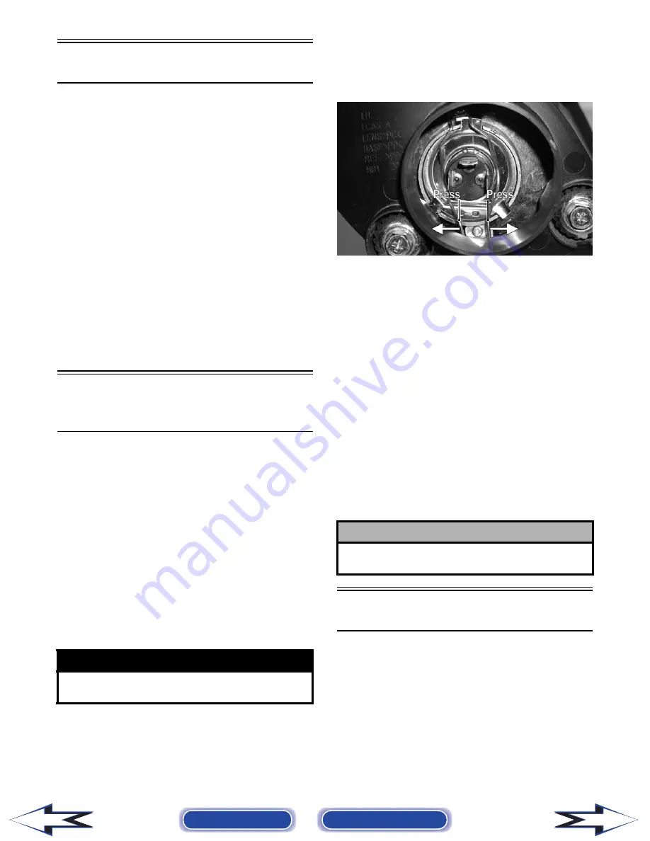
To replace the headlight bulb, use the following pro-
cedure.
1. Remove the boot from the back of the headlight
housing; then remove the three-wire connector
from the bulb.
2. Using care not to bend or deform the spring clip,
release the two ends of the spring clip from the
light housing; then remove the bulb from the
headlight housing.
KM192A
3. Install the new bulb into the headlight housing;
then secure with the spring clip.
4. Connect the three-wire connector to the bulb;
then install the boot.
TAILLIGHT-BRAKELIGHT
To replace the taillight-brakelight bulb, use the fol-
lowing procedure.
1. Remove the two screws and remove the lens
cover.
2. Push the bulb in and turn it counterclockwise.
3. Install the new bulb by turning it clockwise
while pushing in.
4. Install the lens cover.
Switches
Each time the ATV is used, switches should be
checked for proper operation. Use the following list
for reference.
A. Ignition switch — engine will start.
B. Emergency stop switch — engine will stop.
C. Reverse switch — reverse indicator light will
illuminate.
! WARNING
Do not attempt to remove the bulb when it is hot.
Severe burns may result.
! CAUTION
Tighten the lens cover screws only until they are
snug.
Back to TOC
Back to Section TOC
Next
Back
Summary of Contents for DVX 250 2007
Page 1: ......


