


DCS SERIES OPERATION MANUAL
SECTION 8: MASTER/SLAVE OPERATION
Entire Contents Copyright
2018 by Adaptive Power Systems, Inc. (APS) • All Rights Reserved • No reproduction without written authorization from APS.
6RL Series Regenerative DC Load Operation Manual
Page 192 of 204
Slave units will show the alarm “MSP” in the display as long as they not have been
initialized by the master. The same alarm is signaled after a connection drop to the
master unit occurred.
In case the function generator of the master unit is going to be used, the Share bus must
be connected as well
How to connect the digital master-slave bus:
1.
Switch off all units that are to be connected and connect them with network cables
(CAT3 or better, cables not included). It does not matter which of the two master-slave
connection sockets (RJ45, rear panel) is connected to the next unit.
2.
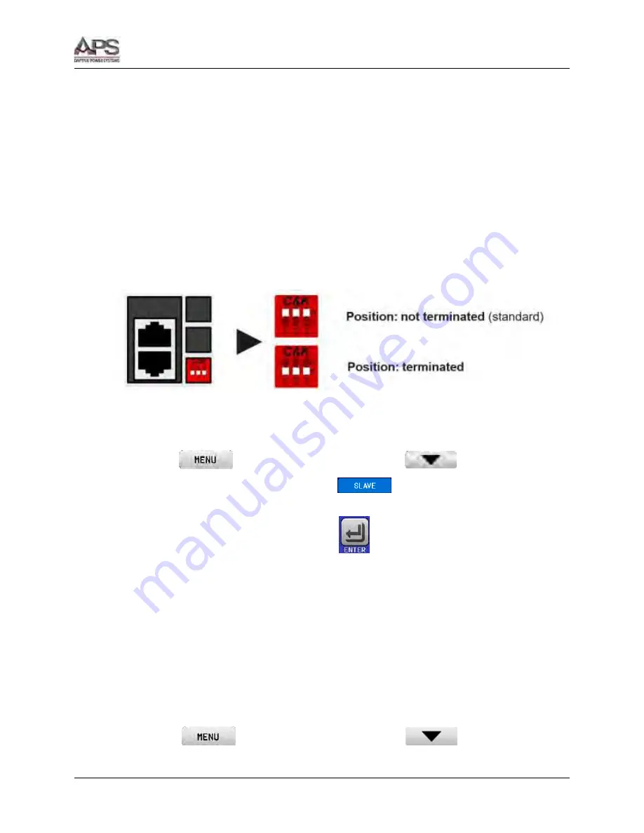
Depending on the desired configuration the units can then be connected at the DC side.
The two units at the beginning and end of the chain should be terminated, if long
connection cables are used. This is achieved using a 3-pole DIP-switch, which is
positioned on the rear panel of the unit next to the M/S connectors.
Now the master-slave system has to be configured on each other unit. It is recommended to
configure all the slave units first and then the master unit.
Step 1: Configuring all slave units (standard 6RL Series models with display)
1.
Enter
then GENERAL SETTINGS and press
until reaching PAGE 8.
2.
Activate the MS mode with touch area
. A warning requester will appear
which has to be acknowledged with OK, otherwise the change will be reverted.
3.
Accept the settings with the touch area
and return to the main page.
Step 1: Configuring all slave units (6RL Series Slave models without display):
1.
Connect the Slave series model via the rear USB port or via Ethernet interface to a PC.
2.
Start the Power Control software (included with the unit on USB stick) and let the
software find the unit.
3.
Open the app “Settings” for the particular unit, change to tab “Master-Slave” and there
set the parameter “Master-slave mode” to “SLAVE”. The slave address is not required to
be set, if shown (depending in the version of the software).
The slave now then configured for master-slave. Repeat the procedure for all other slave units.
Step 2: Configuring the master unit:
1.
Enter
then GENERAL SETTINGS and press
until reaching PAGE 8.
Summary of Contents for 6RL Series
Page 203: ......


