


Setup Pages and Descriptions
67
NXD-700i & NXT-CA7 7” Modero Touch Panels
2.
Within the
Tools
menu, press the
Panel Logs
button. All connection data is contained in the section
Connection Logs
.
Refreshing the Panel Connections Log
1.
From the
Protected Setup
page, press the
Tools
button. This opens the
Tools
menu.
2.
Within the
Tools
menu, press the
Panel Logs
button.
3.
Push the
Refresh
button.
Clearing the Panel Connections Log
1.
From the
Protected Setup
page, press the
Tools
button. This opens the
Tools
menu.
2.
Within the
Tools
menu, press the
Panel Logs
button.
3.
Push the
Clear
button and confirm your selection.
Panel Statistics Page
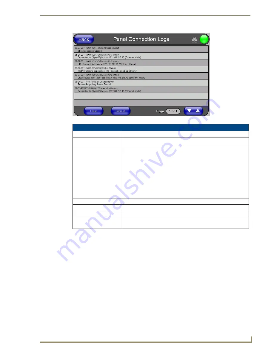
FIG. 65
Panel Connection Logs page
Panel Connection Logs Page
Back:
Saves all changes and returns to the previous page.
Wired icon:
The icon to the left of the Connection Status Icon displays that the current
connection to the Master is
Wired
(image of three networked computers).
Connection Status icon:
The icon in the upper-right corner of each Setup page shows online/offline state
of the panel to the master.
• Bright red - disconnected
• Bright green - connected. Blinks when a blink message is received to dark
green every 5 seconds for half a second then go back to bright green.
• Bright yellow - panel missed a blink message from the master. It will remain
yellow for 3 missed blink messages and then turn red. It will return to green
when a blink message is received.
Note
: a Lock appears on the icon if the panel is connected to a secured NetLinx
Master.
Connection Logs:
A history of all connections, attempts, and failures for the panel.
Clear:
Clears the Connection Logs history.
Refresh:
Refreshes the Connection Logs history.
Page:
Indicates the current page of the Connection Logs.
Use the Up and Down arrows to move from one page to the next.
Summary of Contents for NXD-700i
Page 4: ......
Page 12: ...viii NXD 700i NXT CA7 7 Modero Touch Panels Table of Contents...
Page 30: ...NXT CA7 Installation 18 NXD 700i NXT CA7 7 Modero Touch Panels FIG 19 RJ 45 wiring diagram...
Page 52: ...Configuring Communication 40 NXD 700i NXT CA7 7 Modero Touch Panels...
Page 138: ...Programming 126 NXD 700i NXT CA7 7 Modero Touch Panels...
Page 148: ...Appendix A Text Formatting Codes 136 NXD 700i NXT CA7 7 Modero Touch Panels...
Page 151: ...Appendix B Complex Script Support 139 NXD 700i NXT CA7 7 Modero Touch Panels...


