Installation and Setup
21
Epica DGX 144 Instruction Manual
Safety Recommendations for Laser Products
Important:
No user serviceable parts are inside an AMX AutoPatch product; service should only be
done by qualified personnel.
Caution:
Use of controls or adjustments or performance of procedures other than those specified
herein may result in hazardous radiation exposure.
Exercise caution when installing DGX products to avoid direct eye exposure to invisible laser radiation.
Follow the recommendations below whenever installing or working with DGX products.
Be sure to apply the power only after all fiber connections are made and no fiber ends are
exposed.
Do
not
remove dust plugs from SC fiber connectors or the dust caps from the fiber cables until
establishing connections;
avoid direct eye exposure
.
Make sure all cables, including fiber cables, are correctly connected and/or terminated.
Before you unplug a fiber cable on an input board, disconnect the power on the DGX TX that
is connected to the input.
Before you unplug a fiber cable on an output board, disconnect the switch for that output
connector.
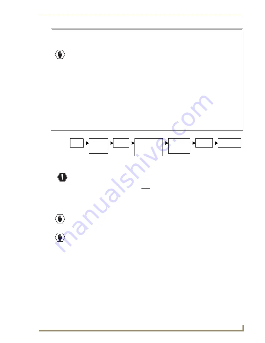
Installation Flow Chart
To install and setup an Epica DGX 144:
Warning:
This product must be installed within a restricted access location where access is through
the use of a tool, lock and key, or other means of security, and is controlled by the authority
responsible for the location. This product must be installed and maintained only by qualified
technicians (see page 17).
1.
Install the Epica DGX 144 enclosure in a rack (see page 22).
2.
If applicable – For multiple-enclosure systems, link them according to the instructions provided
(see page 23).
Caution:
On systems with SC Fiber boards, we recommend using the provided cable management
bars or some other type of cable management system to avoid damage to the fiber cables.
3.
If applicable – For systems with SC Fiber boards, install cable management bars (see page 23).
CAUTION:
CLASS 3R INVISIBLE LASER RADIATION WHEN OPEN; AVOID DIRECT EYE
EXPOSURE.
4.
Attach
only
the first two source and destination devices (see page 36).
5.
If applicable – For boards that require DGX SC Fiber modules, you will also need to install them for
the first two source and/or destination devices (see the module’s documentation).
6.
Attach the external control device (see page 30).
7.
Attach power cords to all power receptacles on each enclosure, then turn on the entire system
(see page 38).
We recommend using a single surge protector
(20 A)
and/or an AC line conditioner.
8.
Execute a test switch to be sure the system is working properly (see page 41).
9.
When the test switch works correctly, attach the remaining source and destination devices and any
additional DGX SC Fiber modules.
FIG. 7
Installation procedure
Install
in rack
If multiple -
enclosure
system, link
enclosures
Attach
controller
Attach 1st two input
and output cables;
if applicable, install
the DGX SC Fiber
modules
Apply power
to enclosure(s)
and then to
system devices
Execute
test switch
Attach all input
& output cables
Summary of Contents for Epica DGX 144
Page 10: ...Notices 6 Epica DGX 144 Instruction Manual ...
Page 20: ...Overview and General Specifications 16 Epica DGX 144 Instruction Manual ...
Page 48: ...Installation and Setup 44 Epica DGX 144 Instruction Manual ...
Page 54: ...Epica DGX 144 SC Fiber Boards 50 Epica DGX 144 Instruction Manual ...
Page 72: ...Appendix A EDID Programmer 68 Epica DGX 144 Instruction Manual ...
Page 82: ...Appendix B Managing Configuration Files 78 Epica DGX 144 Instruction Manual ...
Page 106: ...Appendix E Board Replacement 102 Epica DGX 114 Instruction Manual ...


