User Manual – Rev J
CS Series
California Instruments
93
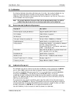
Output gain is set at the factory and the output calibration coefficients are pre-set. They is no
need to change the factory default settings unless any of the following conditions occurs:
1. Replacement of one or more amplifiers as a result of a service action.
2. Replacement of the current limit board. (CI P/N 7004-703-3)
3. Replacement of the controller board. (CI P/N 7004-715-4)
If the output gains are found to be out of tolerance, they need to be adjusted. This requires
removal of the top cover and should only be done by qualified service personnel. In that case,
refer to the non-routine gain calibration section.
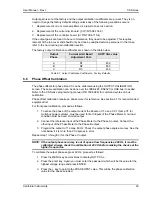
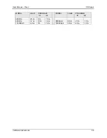
The factory output calibration coefficients are shown in the table below.
Output
Phase
Current Limit Board
Adjustment Pots
OUTP CAL value
A R1
450
B R2
450
C R3
450
Table 6-1: Output Calibration Coefficients - Factory Defaults.
6.6
Phase Offset Calibration
The phase offsets for phase B and C can be calibrated using the OUTPUT CALIBRATION
screen. The same calibration can be done over the IEEE-488, RS232C or USB bus if needed.
Refer to the CS Series programming manual (P/N 7004-988) for command syntax on bus
calibration.
Phase offset calibration requires a phase meter for reference. See section 6.1 for recommended
equipment list.
For front panel calibration, proceed as follows.
1. To sense the phase of the output current the Pearson CT, use a 0.01 V/amp CT for
multi-box power systems, must be used for both inputs of the Phase Meter. A no-load
condition must be used, shorted output.
2. Connect the reference input of the Phase Meter to the Phase A output. Connect the
other input of the Phase Meter to the Phase B output.
3. Program the output to 11 amps, 60 Hz. Check the output phase angle accuracy. See the
note below if it is more than 0.5 degrees in error.
Repeat step 1) through 3) for the Phase C output.
NOTE: If the output phase accuracy is out of spec at low frequencies, 400 Hz, it must be
calibrated. Always check the calibration at 400 Hz before making the checks at the
higher frequencies.
To calibrate the output phase angle at 60 Hz, proceed as follows:
1. Press the MENU key several times to display OUTP CAL.
2. Press the enter key. Again you must enter the password, which will be the value for the
highest voltage range and press ENTER.
3. Press
the
↓
key to point to the PHASE OFST value. This will be the phase calibration
value for the phase selected.

