


User Manual – Rev J
CS Series
California Instruments
9
List of Figures
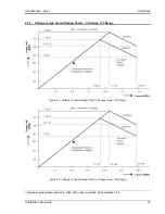
Figure 2-1: Voltage / Current Rating Chart in 3 phase mode, 135 Range. .......................................................... 15
Figure 2-2: Voltage / Current Rating Chart in 1 phase mode, 135 Range. .......................................................... 15
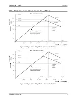
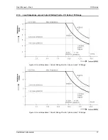
Figure 2-3: Voltage / Current Rating Chart in 3 phase mode, 270 Range. .......................................................... 16
Figure 2-4: Voltage / Current Rating Chart in 1 phase mode, 270 Range. .......................................................... 16
Figure 2-5: Load Impedance / Current Rating Chart in 3 phase mode, 135 Range. ............................................ 17
Figure 2-6: Load Impedance / Current Rating Chart in 1 phase mode, 135 Range. ............................................ 17
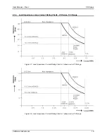
Figure 2-7: Load Impedance / Current Rating Chart in 3 phase mode, 270 Range. ............................................ 18
Figure 2-8: Load Impedance / Current Rating Chart in 1 phase mode, 270 Range. ............................................ 18
Figure 3-1: Rear Panel Connector Locations – CS Series ................................................................................... 30
Figure 3-2: 9000CS/2 Output Wiring ................................................................................................................... 33
Figure 3-3: 9000CS/2 Wiring diagram - 3 Phase mode ....................................................................................... 34
Figure 3-4: 13500CS/3 Wiring diagram - 3 Phase mode ..................................................................................... 35
Figure 3-5: 18000CS/4 Wiring diagram - 3 Phase mode ..................................................................................... 36
Figure 3-6: USB Connector pin orientation. ......................................................................................................... 40
Figure 3-7: Functional Test Setup ....................................................................................................................... 43
Figure 3-8: Clock and Lock Connections ............................................................................................................. 46
Figure 3-9: CSGui Windows application software ................................................................................................ 47
Figure 4-1: Shuttle Knob ...................................................................................................................................... 51
Figure 4-2: Menu Keys ........................................................................................................................................ 52
Figure 4-3: Measurement Screen ........................................................................................................................ 54
Figure 4-4: PROGRAM Menu .............................................................................................................................. 60
Figure 4-5: CONTROL Menus ............................................................................................................................. 61
Figure 4-6: MEASUREMENT Screen .................................................................................................................. 64
Figure 4-7: Selecting a Waveform ....................................................................................................................... 79
Figure 4-8: Selecting Waveforms for Single Phase or All Phases ....................................................................... 80
Figure 4-9: Waveform Crest Factor Affects Max. RMS Current. .......................................................................... 80
Figure 4-10: Switching Waveforms in a Transient List ......................................................................................... 85
Figure 4-11: TRANSIENT Menu .......................................................................................................................... 85
Figure 6-1: Location of Gain pot adjustments ...................................................................................................... 94
List of Tables
Table 3-1: Output Terminal connections. ............................................................................................................. 32
Table 3-2: Rear Panel Connectors ...................................................................................................................... 37
Table 3-3: AC Input Terminal Block Connection Description ............................................................................... 38
Table 3-4: SMA Connectors – CS Series ............................................................................................................ 38
Table 3-5: BNC Connectors ................................................................................................................................. 39
Table 3-6: External Sense Connector .................................................................................................................. 39
Table 3-7: RS232C Connector ............................................................................................................................ 39
Table 3-8: USB Connector pin out. ...................................................................................................................... 40
Table 3-9: RJ45 LAN Connector pin out. ............................................................................................................. 41
Table 3-10: Full Load Resistance – CS Series .................................................................................................... 43
Table 4-1: Menu Tree .......................................................................................................................................... 59
Table 4-2: Factory Default Power on Settings ..................................................................................................... 86
Table 4-3: Factory Default Power on Settings ..................................................................................................... 87
Table 6-1: Output Calibration Coefficients - Factory Defaults. ............................................................................. 93
Table 6-2: Output Calibration Coefficients - Factory Defaults. ............................................................................. 95
Table 7-1: Basic Symptoms ................................................................................................................................. 97
Table 7-2: Replaceable Parts and Assemblies .................................................................................................. 102
Table 8-1: Error Messages ................................................................................................................................ 108