User Manual – Rev J
CS Series
California Instruments
29
3. Unpacking and Installation
3.1 Unpacking
Inspect the unit for any possible shipping damage immediately upon receipt. If damage is
evident, notify the carrier.
DO NOT
return an instrument to the factory without prior approval.
Do not destroy the packing container until the unit has been inspected for damage in shipment.
If possible, retain the container in the event the system ever has to be returned to the factory for
either repair of upgrades
WARNING: This power source weighs approximately
175 lbs / 79.2 Kg per chassis (2
chassis total)
Obtain adequate help when moving or installing the unit. Make sure the
cabinet and rack slides used to install the CS Series unit(s) can support the weight of
the unit(s).
3.2 Power
Requirements
The CS Series power Source has been designed to operate from a three-phase, three wire
(Wye or Delta) AC input line. A protective earth connection is required as well. (PE).
Available three-phase input setting is 208 to 230 V
LL
nominal for standard CS models or 400 V
LL
nominal for CS Series with option –400. All three phase input is three wire plus ground.
CAUTION: Do not connect 400V into a unit designed for 208 use. The result could be
a severely damaged unit. Always check the input rating on the model number tag
before connecting AC input power. AC voltage input settings CANNOT be changed in
the field.
3.3 Mechanical
Installation
The CS Series AC power sources can be used free standing on a solid surface or mounted in a
19” instrument cabinet. The units are fan cooled, drawing air in from the side and exhausting at
the rear. The back of each unit must be kept clear of obstruction and a 3” clearance must be
maintained to the rear. Special consideration of overall airflow characteristics and the resultant
internal heat rise must be considered at all times to avoid self heating and over temperature
problems.
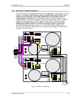
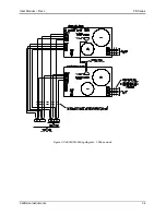
Multi chassis configurations such as the 9000CS/2 consist of two self-contained 4500CS power
sources. They must be connected through the system interface using the supplied DB25 to
DB25 cable. Output wiring from each chassis to the EUT must be of
equal wire gage and
length
to ensure proper current sharing between units.
Note that for multi-chassis systems, it is recommended to turn the Master unit ON first and then
the Auxiliary unit(s). To turn the system off, turn OFF the Auxiliary unit(s) first and then the
Master unit.

