User Manual – Rev J
CS Series
California Instruments
32
Note: The output of the power source is isolated from the input line and floating with
respect to chassis ground. If needed, either side (HI or LO) may be grounded.
The output power cables must be large enough to prevent a total voltage drop exceeding the
programmed voltage limit or 135 Vrms across the terminals of the current source. Note that
wires must be sized to accommodate the maximum current that is available. Always use the
current rating size the wires.
Cable lengths must not exceed twenty-five (25) feet. For lengths greater than 25 feet, calculate
the voltage drop from the following formula:
2 X DISTANCE X CABLE RESISTANCE PER FT. X CURRENT = VOLT DROP
Note: Ensure that output cable lengths from Master and Auxiliary chassis to EUT are of
identical length.
3.5.2
Output Terminal Block – OUTPUT (TB1)
Each CS chassis has a single AC output terminal block. For tabletop operation of a single
chassis system, the output terminal block must be covered using the supplied AC Output safety
cover. The terminal blocks are large enough to accommodate required wire gauge sizes. The
terminal block is located in the upper left corner on the rear panel of the unit. (Looking from the
back).
Multi-chassis configurations have two or more output terminal blocks, one on the master CS
chassis and one on the auxiliary CS chassis.
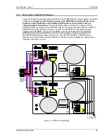
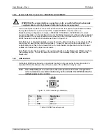
For operation as a multi-chassis system, the outputs of all CS chassis’ must be connected
together using the additional terminal blocks provided in the CS ship kit.
Keep the wire lengths
between each chassis and this common terminal block the same.
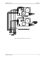
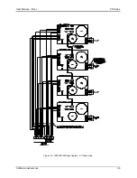
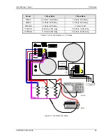
See Figure 3-2 for output wiring diagram.
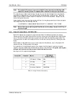
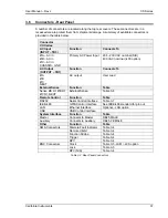
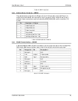
Connector
Terminal
Mode
CS Output
OUTPUT (TB1)
1
3 Phase & 1 Phase
ØA
2
3
Phase ØB
3
3 Phase
ØC
4
Common / Neutral
NEUTRAL
Table 3-1: Output Terminal connections.

