background image

MEGAPOWER 48 / ADTTE  

8200-0170-05, REV. A 

OPERATION AND PROGRAMMING REFERENCE GUIDE


1 of 43 

Using MegaPower

®

 48 Matrix Switcher with 

ADTTE Keyboard Controller 

Operation and Programming Reference Guide 

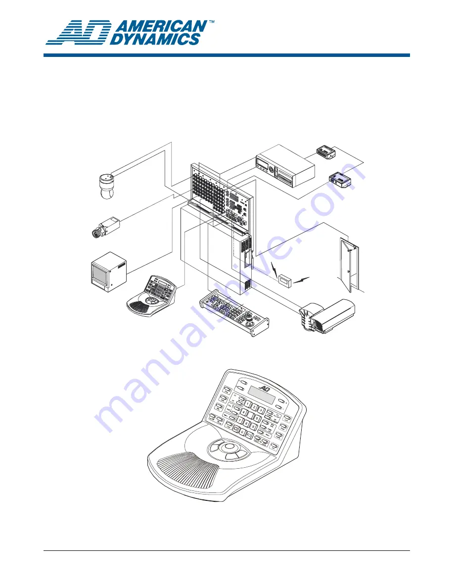
Figure 1: MegaPower 48 (MP48) Typical Configuration 


Digital

Video Recorder

Recorder Control

Devices

Alarm

Input

PTZ

Pager

AD2088

Keyboard

ADTTE

Touch Tracker

Keyboard

Monitor

Camera

Programmable

Dome

MegaPower 48

Matrix Switcher/

Controller System


Figure 2: ADTTE Keyboard Controller 

n

5

xt


© 2004 Sensormatic Electronics Corp. 

Summary of Contents for ADTTE

Page 1: ...ation and Programming Reference Guide Figure 1 MegaPower 48 MP48 Typical Configuration Digital Video Recorder Recorder Control Devices Alarm Input PTZ Pager AD2088 Keyboard ADTTE Touch Tracker Keyboar...

Page 2: ...ings 23 Changing Monitor Settings 27 Changing Camera Settings 28 Configuring User or Keyboard Settings 30 Configuring Switching Settings 33 System Partitioning 37 Configuring Alarms 39 Declarations 43...

Page 3: ...ystem priority levels and user password Monitor tours On screen text includes displaying video input number monitor status time date information and titles for cameras presets alarms 64 universal tour...

Page 4: ...the keypad e The Status field shows the current operating state of the system During normal operation Program mode P appears in this field During system menu programming M appears in this field Durin...

Page 5: ...te mode Displays page to left in Menu mode Auxiliary ON Page Right Multi function key that is used activate an auxiliary device in Monitor Operate mode Displays page to right in Menu mode F Pswd Sets...

Page 6: ...during menu programming U User Used to authorized users to log on to the system V Mon Arm On Used to enable system alarms to appear on monitors This feature is under keyboard lock protection Mon Arm...

Page 7: ...can begin performing other tasks Logging Off When the MP48 system is not in use you should log off the system This will ensure that unauthorized users cannot control your system 1 Enter 99 2 Press F1...

Page 8: ...s Appendix B of the MegaPower 48 Programming and Operation Manual includes a complete list of the status messages C Camera Title Up to 16 characters may be used for the camera title Depending on the f...

Page 9: ...the Tracker Ball moves Figure 8 ADTTE Tracker Ball control diagonal movement Note For cameras with variable speed pan tilt capability camera movement speed is proportional to the positioning of the T...

Page 10: ...the numeric keypad Figure 11 Shot Preset and Pattern keys Shot Enter Pattern Exit To call a preset 1 Press to the right of the LCD This ensures that the Touch Tracker is in recall mode 2 Call the came...

Page 11: ...nitor screen for a specified dwell time In addition each preset or pattern can have a pre programmed preset status auxiliary status and connect next designation The Run and Hold keys are located to th...

Page 12: ...atched auxiliary remains activated A momentary auxiliary is deactivated 4 To de activate a latched auxiliary press Auxiliary Off Acknowledging Alarms System cameras may be associated with alarm contac...

Page 13: ...Salvo key Run Hold Salvo To call a salvo 1 Enter the number of the first lowest numbered monitor in the salvo group 2 Press Monitor 3 Enter the salvo number 1 64 4 Press Salvo The salvo will appear o...

Page 14: ...amming mode is active Locking the Keyboard When programming tasks are finished lock the keyboard 1 Enter the keyboard lock password 2 Press Lock The lower right corner of the LCD displays L indicating...

Page 15: ...ontain up to 64 camera scenes sequenced in any order Each scene is shown for a specified duration called the dwell time Note Verify that the keyboard is in programming mode before performing this task...

Page 16: ...s all subsequent alarms are held in queue until displayed alarms are cleared Alarm Queuing Methods Two alarm queuing methods are available Sequence and Hold Queuing Sequence Queuing Incoming alarms ar...

Page 17: ...rming this task See Unlock Lock the Keyboard on page 14 To enable or disable manual override 1 Call the desired armed monitor 2 Do one of the following Command Function 17 Mon Arm On Enable manual ove...

Page 18: ...lt in video loss detection Video loss is determined by the absence of a video sync signal at any of the 48 video inputs on the patch panel Loss of the sync signal would occur if a camera is malfunctio...

Page 19: ...Commands all keyboard ports Command Function 46 F2 Enables audio alarms for all keyboard ports 45 F2 Disables audio alarms for all keyboard ports Transferring System Data System data can be transferre...

Page 20: ...e default password is set to 1953 IMPORTANT If you do not change the default password anyone who knows the default password will be able to gain access to the advanced features of the ADTTE keyboard T...

Page 21: ...ssages on the LCD appear in the selected language Displaying the Touch Tracker Baud Setting Enter 3 and press F1 to display the current baud setting for the ADTTE Touch Tracker Changing the Baud Rate...

Page 22: ...he appropriate functions on the multi function keys are used for operating the menus Note The menu functions are printed beneath the primary key function names on the ADTTE keypad appliqu Table 11 Mul...

Page 23: ...settings associated with user access to system cameras monitors and keyboards Alarms configure alarm titles alarm contacts and enables alarm association with system monitors In addition you can config...

Page 24: ...ss Exit Pattern to return to the previous menu when finished making changes Changing Time and Date Settings Use Time and Date to configure settings associated with year and date format current date an...

Page 25: ...IMPORTANT Once the selections for a port have been made do not change the settings unless the connected devices are changed as well Port Usage Notes Setting Description Alarm Use this setting when co...

Page 26: ...is present N indicates loss of sync Configuring Paging Profiles Use Paging Profile to create special profiles for sending messages to paging devices E D I T P A G I N G P R O F I LE 01 1 2 3 4 5 6 7 8...

Page 27: ...k Y yes Enables manual acknowledgement for instant and auto clear arming codes N no Disables manual acknowledgement for instant and auto clear arming codes Note This feature must be programmed after t...

Page 28: ...n a system reset all pseudo numbers are reset to the real default camera numbers To assign or change a Pseudo Camera Number 1 Enter the Real and press Page Up Iris Close or Page Down Iris Open 2 Enter...

Page 29: ...to the previous menu Changing Preset Titles Use Preset Titles to program a 2 line 16 character title that appears whenever a preset is displayed P R E S E T T I T LE T I T LE A B C D E FG H I JK LM N...

Page 30: ...r Note Entering a preset title number greater than 4096 such as 9999 removes the preset title association 3 Repeat steps 1 and 2 for each preset number associated with the designated camera number Whe...

Page 31: ...ng changes press Exit Pattern to return to the previous menu Note The default passcode for User 1 is 914365 This passcode should be changed to prevent unauthorized access to the system Changing Keyboa...

Page 32: ...hat is being configured Add User Y Yes New users can be added N No New users cannot be added System Reset Y Yes System reset allowed via keyboard commands N No System reset not allowed via keyboard co...

Page 33: ...n PR or PT Represents a preset PR or pattern PT that is called when a camera is selected Aux Auxiliary Activates the relay associated with the selected camera for auxiliary control If no auxiliary act...

Page 34: ...t of the AUX column and the appropriate entry row b Press Enter Shot to display the auxiliary options 1 1 ON 5 1 OFF 2 2 ON 6 2 OFF 3 3 ON 7 3 OFF 4 4 ON 8 0 no action Note If the Connect Next field i...

Page 35: ...Shot Note Press Enter Shot without entering a camera salvo number to remove the camera entry 3 Set the function to call a preset or pattern a Move the cursor to the cross point of the FUNCT column and...

Page 36: ...er Shot 4 Edit the event timer a Move the cursor to the Edit Timer line and press Enter Shot to display the Event Timers screen E V E N T T I M E R S T I M E 12 00 D A Y O F W E E K M O N S M T W T F...

Page 37: ...itioning Keyboards and Monitors Use Keyboard Monitor to specify which keyboards have access to which monitors K E Y B O A R D M O N I T O R M O N 01 02 03 04 05 06 07 08 0001 Y Y Y Y Y Y Y Y 0002 Y Y...

Page 38: ...Repeat steps 1 and 2 for each keyboard camera you want to change Press Exit Pattern to return to the previous menu Partitioning Keyboards and Camera Control Use Keyboard Camera Control to specify whi...

Page 39: ...nt to change Press Exit Pattern to return to the previous menu Configuring Alarms Use the Alarms menus to configure alarm messages configure RS 232 dome and video loss alarms and associate alarms to m...

Page 40: ...and clearance methods The following illustrates the Patch Panel Setup menu however RS 232 Dome and Video Loss setup menus include the same settings P A T C H P A N E L S E T U P A LA R M 0001 0002 00...

Page 41: ...is manually acknowledged all members of the wired set will be cleared To setup alarms 1 Select the alarm type patch panel RS 232 dome or video loss from the Alarm Setup menu 2 Locate the alarm contact...

Page 42: ...t will be cleared c When the appropriate choice is displayed press Next to advance to the next field 12 When finished making changes press Exit Pattern to return to the previous menu Associating Alarm...

Page 43: ...or on the web at www americandynamics net WARRANTY DISCLAIMER Sensormatic Electronics Corporation makes no representation or warranty with respect to the contents hereof and specifically disclaims an...

Reviews: