41978 AMD RS690M Databook 3.06
© 2008 Advanced Micro Devices, Inc.
2-4
Proprietary
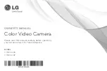
Side-port Memory Interface (RS690T Only)
Figure 2-4 RS690T Side-port Memory Interface
2.2.1.1 Supported DDR2 Components
The memory controller supports DDR2 SDRAM chips in several configurations. These chips are organized in banks,
rows (or pages), and columns. The supported DDR2 components have four or eight banks.
lists the supported
memory components.
2.2.1.2 Row and Column Addressing
shows how the physical address P (after taking out the bank bit) is used to provide the row and column
addressing for each size of DDR2 memories.
Table 2-2 DDR2 Memory Row and Column Addressing
Table 2-1 Supported DDR2 Components
DDR2 SDRAM
Mbytes
Config
Mbits
CS Mode
Bank Bits Row Bits
Col Bits
16Mbits x 16 256
4
2
13
9
32
32Mbits x 8
256
5
2
13
10
64
32Mbits x 16 512
10
2
13
10
64
64Mbits x 8
512
6
2
14
10
128
64Mbits x 16 1024
11
3
13
10
128
Address
A13 A12 A11
A10 A9
A8
A7
A6
A5
A4
A3
A2
A1
A0
16Mbits x16 devices
Row
P10
P14
P13
P12
P11
P22
P21
P20
P19
P18
P17
P16
P15
Column
-
-
PC
-
P9
P8
P7
P6
P5
P4
P3
P2
P1
32Mbits x8 devices
Row
P23
P14
P13
P12
P11
P22
P21
P20
P19
P18
P17
P16
P15
Column
-
-
PC
P10
P9
P8
P7
P6
P5
P4
P3
P2
P1
Data Mask
MEM_DM[1:0]
Data
MEM_DQ[15:0]
2
4
16
RS69
0T Side-
port
Me
mory
Int
e
rf
ace
Data Strobes
MEM_DQS[1:0]P/N
Un-buffered DD
R2
SDRA
M
MEM_CKE, MEM_RAS#,
Differential Clocks
MEM_CKP/MEM_CKN
4
2
MEM_CAS#, MEM_WE#
14
Address
MEM_A[13:0]
1
Chip Select
MEM_CS#
1
On-Die Termination
MEM_ODT
3
Bank Address
MEM_BA[2:0]
MEM_CALN
MEM_CALP
VDD_MEM