


APPENDIX D: DEFINING THE OPTIMUM PROCESS
UB25 LINEAR DC RESISTANCE WELDING CONTROL
990-665
D-7
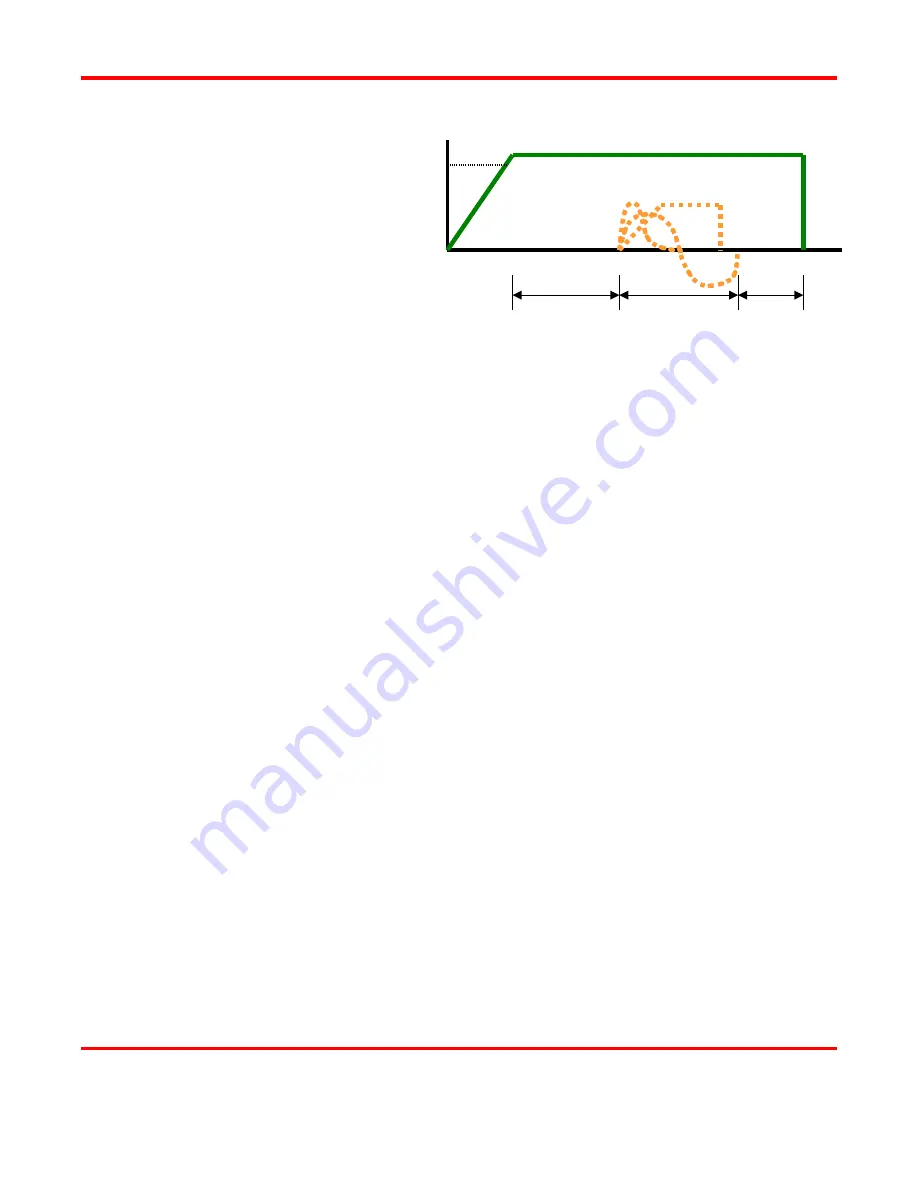
The figure on the right
shows a typical welding
sequence where the force is
applied to the parts; a
squeeze time is then initiated
which allows the force to
stabilize before the current is
fired. Squeeze time also
allows time for the contact
resistances to reduce as the
materials start to come into
closer contact at their interface. A hold time is the initiated after current flows to allow the parts to cool
under pressure before the electrodes are retracted from the parts. Hold time is important as weld strength
develops in this period of time. This basic form of weld profile is sufficient for the majority of small part
resistance welding applications.
Power supply technology selection is based on both the requirements of the application and process. In
general, closed loop power supply technologies are the best choice for their consistent, controlled output
and fast response to changes in resistance during the weld.
Approach to Weld Development
The first stage in developing a quality welding process is to fix as many of the variables as possible in the
welding equipment set up. The welding variables can be grouped in the following categories:
•
Material variables
−
Base material
−
Plating
−
Size
−
Shape
•
Weld head & mechanical variables
−
Force, squeeze, hold
−
Actuation method
−
Electrode material and shape
•
Power supply variables
−
Energy
−
Time (squeeze, weld, hold)
•
Process variables
−
Tooling, level of automation
−
Repetition rate
−
Part positioning
−
Maintenance, electrode cleaning
•
Quality requirements
−
Pull strength
−
Visual criteria
−
Test method, other weld joint requirements
Squeeze
Heat
Hold
Welding Force
Trigger Force
Current


