Printed Documentation
18
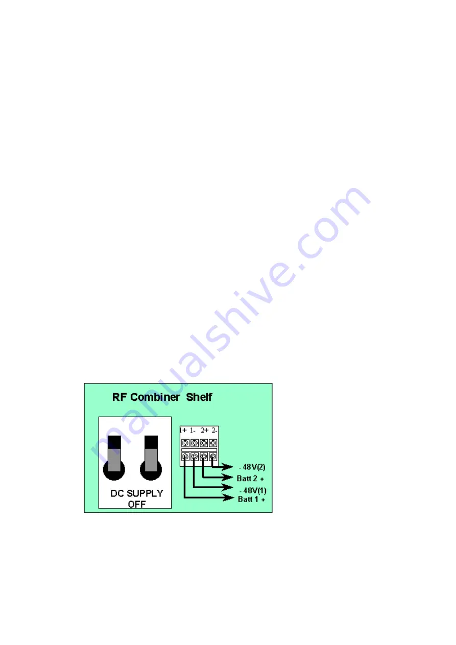
Dual Supply: Both feeds are fed from the same Distribution Boards (DB) and separately
fused so that in the event of one fuse failing the rack is supplied via the other fuse. Run
and tie in two negative battery feeds and a two zero volt returns from the Distribution
Board to a Dual Pole Isolating switch and then from the isolating switch to the to the
AC/CT rack installed. These supplies should be rated at 30A. Power cables must be run
and tied separate from signal cables. (see diagram above and note 2 below).
Single Supply: Is the least preferred option as a blown fuse causes the total loss of
supply to the rack but because there is only one supply the fuse can act as an isolation
point and there is no need for a separate isolation switch as required on the other
options. Run and tie in a negative battery feed and a zero volt return from the Distribution
Boards to the AC/CT rack installed. The two inputs to the Combiner Shelf/Fuse and
Alarm Panel should be looped together as shown in the diagram above. This ensures
that the alarms on the PSU are extinguished when a supply is present.
From the site survey confirm the location of the isolator for the negative battery feed points;
then ensure that the supply is isolated. If the location is remote from the AC Rack, take
appropriate action to ensure that the supply is not inadvertently reconnected. This may
include locking OFF an isolator, removing fuses and ensuring that replacement fuses are not
easily installed. Provide a label at the AC Rack to indicate the location of the isolator or fuse
positions mentioned above.
To provide security of supply two separate Distribution Boards (DB) should be used to supply
DC to each rack (see note 2 below) Run and tie in a negative battery feed and a zero volt
return to the AC/CT rack installed from the DB. Run and tie in a second negative battery feed
and a zero volt returns to the AC/CT rack installed from a second DB, if a second distribution
board is available. If only one source of supply is available the both supplies may be run from
the same DB These supplies should be rated at 30A. Power cables must be run and tied
separate from signal cables.
DC Cabling Central Terminal Modem Rack/Integrated Basestation
Run the DC cables through the top right hand side of the rack, loosen the screws on the
Combiner Shelf and slide the screen to the right. Place the DC cables behind the screening
and though to the connection block at the lower right of the Combiner Shelf. Return the
screen to its original position. Re-tighten the Combiner shelf screws.
Trim cables and strip 7mm to insert into the termination block. Terminate the cables on the
Combiner Shelf at the appropriate connection points. The negative supplies go to Termination
Block 2 & 4. The positive battery returns go to 1 & 3.
DC Termination on The Combiner Shelf.
DC Termination on Fuse and Alarm Panel (AS4000 Access Concentrator
and AS4000 Expansion Rack)
Run the DC cables through the top left hand side of the rack, into the fuse and alarm panel.
Summary of Contents for AS4000
Page 2: ......
Page 6: ...Printed Documentation 2 ...
Page 14: ...Printed Documentation 10 ...
Page 16: ...Printed Documentation 12 ...
Page 27: ...Installation 23 Typical 75ohm DDF Layout ...
Page 28: ...Printed Documentation 24 ...
Page 41: ...Installation 37 ...
Page 42: ...Printed Documentation 38 BNC Terminations to Coax ...
Page 43: ...Installation 39 Type 43 Terminations to Coax ...
Page 44: ...Printed Documentation 40 ...
Page 52: ...Printed Documentation 48 ...
Page 68: ...Printed Documentation 64 ...
Page 71: ...Installation 67 ...
Page 72: ...Printed Documentation 68 CT Rack Labelling Central Terminal Rack ...
Page 73: ...Installation 69 BNC Terminations to Coax ...
Page 74: ...Printed Documentation 70 Type 43 Terminations to Coax ...
Page 75: ...Installation 71 ...
Page 78: ...Printed Documentation 74 Card Insertion DA Rack Card Insertion Expansion Rack ...
Page 110: ...Printed Documentation 106 ...
Page 112: ...Printed Documentation 108 Combiner Shelf PSU ...
Page 133: ...Setup and Test 129 ...
Page 163: ...Setup and Test 159 ...
Page 166: ......
Page 170: ...Printed Documentation 166 ...
Page 176: ...Printed Documentation 172 ...
Page 192: ......


