32
Networking
The reading of the results data should be done at the rising edge of the
“
Status OK
”
and
“
Status NOK
”.
This will insure the correct results are captured consistently. All the results are zeroed after the
“
Status
OK
”
and
“
Status NOK
”
are turned off.
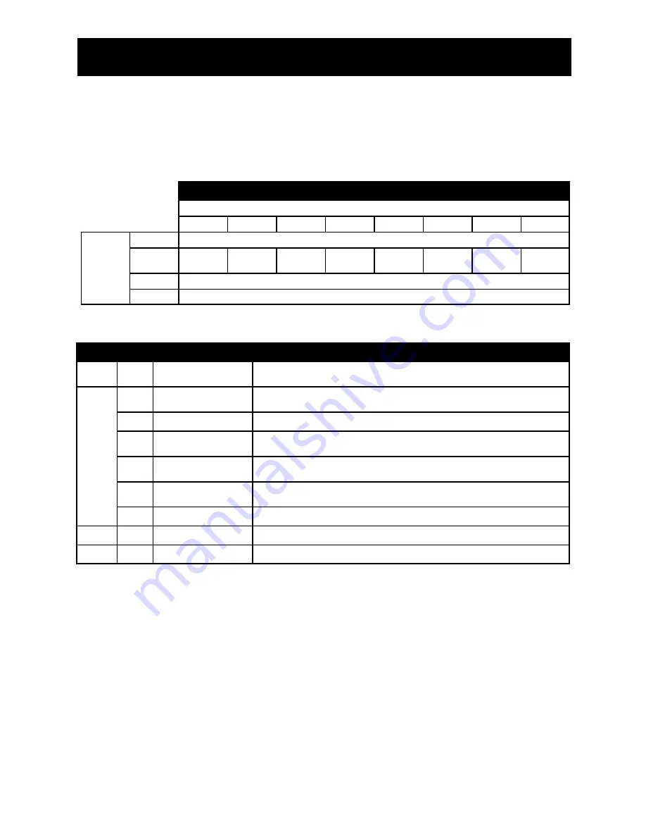
The controller consumes thirty two bytes of inputs (Assembly instance 112).
Controller Inputs
Bit
7
6
5
4
3
2
1
0
Byte
0
PSET
1
PLC
Enable
White
Flash
Pause
Tool
Enable
2-11
Sequence Number
12-31
Serial Number
Byte
Bit
Name
Function
0
0-7
PSET
Set the active parameter set of 1-32. If 0 the active parameter set is left un-
changed.
1
0
Tool Enable
If PLC Enable is 0 this input is ignored. If PLC Enable is 1 this bit can be used
to enable or disable the tool.
1-3
Not used
4
Pause
Setting Pause to 1 cause the light stack to strobe. Setting it to 0 put the light
stack back into its normal operation.
5
White Flash
Setting White Flash to 1 cause the light stack to flash the white light. Setting it
to 0 put the light stack back into its normal operation.
6
PLC Enable
Setting PLC Enable to 1 allows the Tool Enable bit. Setting it to 0 disables the
Tool Enable function.
7
Not used
2-11
0-7
Sequence Number
10 character Sequence Number.
12-31
0-7
Serial Number
20 character Serial Number.
Summary of Contents for iEC
Page 1: ...AcraDyne iEC DC Tool Controllers User Guide...
Page 35: ...35 Appendix B KDM Menu Structures Main Menu Structure Parameter Set up Menu...
Page 36: ...36 APPENDIX B KDM Menu Structures Administration Menu...
Page 45: ...45 Notes...
Page 46: ...46 Notes...
Page 47: ...47 Notes...


