


100
Agilent Intuvo 9000 GC Installation
B
Cabling Diagrams and Remote Start/Stop
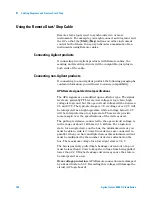
Using the Remote Start/Stop Cable
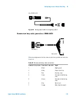
Remote start/stop is used to synchronize two or more
instruments. For example, you might connect an integrator and
the GC so that the [
Start
]/[
Stop
] buttons on either instrument
control both of them. You can synchronize a maximum of ten
instruments using Remote cables.
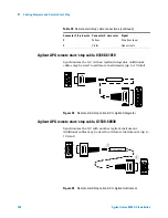
Connecting Agilent products
If connecting two Agilent products with Remote cables, the
sending and receiving circuits will be compatible—just plug in
both ends of the cable.
Connecting non-Agilent products
If connecting to a non-Agilent product, the following paragraphs
contain information you will need to ensure compatibility.
APG Remote signal electrical specifications
The APG signals are a modified open collector type. The signal
levels are generally TTL levels (low voltage is logic zero, high
voltage is logic one) but the open circuit voltage will be between
2.5 and 3.7 V. The typical voltage is 3 V. A voltage over 2.2 V will
be interpreted as a high logic state while a voltage below 0.4 V
will be interpreted as a low logic state. These levels provide
some margin over the specifications of the devices used.
The pull-up resistance, connected to the open-circuit voltage, is
in the range of about 1 kOhms to 1.5 kOhms. For a logic-low
state, for a single device on the bus, the minimum current you
must be able to sink is 3.3 mA. Since devices are connected in
parallel, when you have multiple devices this minimum current
must be multiplied by the number of devices attached on the
bus. The maximum voltage for a low-input state is 0.4 V.
The bus is passively pulled high. Leakage current out of a port
must be less than 0.2 mA to keep the voltage from being pulled
lower than 2.2 V. Higher leakage current may cause the state to
be interpreted as a low.
Over-voltage protection
: APG Remote connections are clamped
by a Zener diode to 5.6 V. Exceeding this voltage will damage the
circuit (GC logic board).
Summary of Contents for Intuvo 9000
Page 1: ...Agilent Technologies Agilent Intuvo 9000 Gas Chromatograph Installation and First Startup...
Page 6: ...6 Agilent Intuvo 9000 GC Installation...
Page 25: ...Installing the GC 1 Agilent Intuvo 9000 GC Installation 25 3 Reinstall the GC covers...
Page 27: ...Installing the GC 1 Agilent Intuvo 9000 GC Installation 27 Turn on the GC...
Page 29: ...Installing the GC 1 Agilent Intuvo 9000 GC Installation 29...
Page 84: ...84 Agilent Intuvo 9000 GC Installation 1 Installing the GC 8 Close the GC front door...
Page 114: ...Agilent Technologies...


