


106
Agilent Intuvo 9000 GC Installation
B
Cabling Diagrams and Remote Start/Stop
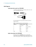
Cable Diagrams
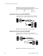
Analog signal cable, general use, G1530-60560
Connects GC signal outputs to non-Agilent products. Also used
for the Analog Input Board (AIB).
The pin assignments for the general use analog out cable are
listed in
.
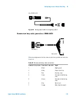
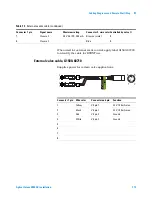
Agilent analog signal cable, G1530-60570
This cable connects an
Analog out
port to an external data
system. Both 0 to 1 volt and 0 to 10 volts are provided. Connects
both GC signal outputs to Agilent 3395B/3396C integrators, and
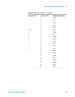
Table 9
Analog cable, general use, output connections
Connector 1
Connector 2, wire color Signal
1
Brown or violet
Not used
2
White
0 to 1 V, 0 to 10 V (–)
3
Red
Not used
4
Black
1 V (+)
6
Blue
10 V (+)
Shell
Orange
Ground
G1530-60560
1
2
3
4
5
6
Connector 1
Connector 2
Summary of Contents for Intuvo 9000
Page 1: ...Agilent Technologies Agilent Intuvo 9000 Gas Chromatograph Installation and First Startup...
Page 6: ...6 Agilent Intuvo 9000 GC Installation...
Page 25: ...Installing the GC 1 Agilent Intuvo 9000 GC Installation 25 3 Reinstall the GC covers...
Page 27: ...Installing the GC 1 Agilent Intuvo 9000 GC Installation 27 Turn on the GC...
Page 29: ...Installing the GC 1 Agilent Intuvo 9000 GC Installation 29...
Page 84: ...84 Agilent Intuvo 9000 GC Installation 1 Installing the GC 8 Close the GC front door...
Page 114: ...Agilent Technologies...


