41
3.5.2 Current output
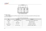
The connection of voltage output is shown in the Figure 14 Current output. Then click the gear switching menu of
channel 2 and select the (0~25)mA .
Figure 14 Current output
3.5.3 Frequency output
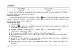
The connection of frequency output is shown in the Figure 13 Voltage, frequency, pulse output. Then click the gear
switching menu of channel 2 and select the (0.01~50k)Hz.
The frequency output function provides a setting menu, in which the amplitude of the frequency output can be set.
3.5.4 Pulse output
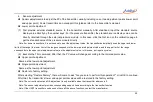
The wiring method of using the pulse output function is the same as the voltage output (Figure 13
voltage/frequency/pulse output). After correct wiring as shown in the figure, click to expand the features switching menu of
channel 2 and select (1~9999999) to switch to the pulse output gear. The pulse output provides a setting menu, and the
amplitude and frequency of the pulse output can be set in the setting menu.
Summary of Contents for 226
Page 1: ...226 227 Multifunction Process Calibrator...
Page 2: ......
Page 3: ...ADT226 227 Multifunction Process Calibrator User Manual Version 2306V01 Additel Corporation...
Page 4: ......
Page 6: ......
Page 31: ...19 1 4 Basic Structure Figure 1 Basic Structure...
Page 33: ...21 Figure 2 Power adaptor...
Page 64: ...52 External module information including external module A and external module B...
Page 107: ...95...


