


45
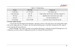
3.5.8 Ramp output
The three electrical output features of voltage, current, and frequency of the calibrator and the two simulate
temperature output features of simulate thermocouple and simulate thermal resistance all support automatic ramp output
mode. The Ramp can increase or decrease the output value smoothly and continuously. In fact, a small step value is used
to form a Ramp signal, which is represented by a Ramp gradient in the calibrator. The calibrator will automatically
calculate the Ramp gradient according to the setting start and end values of the Ramp and the rise and fall time. When the
start value and end value are fixed, the longer the ramp time, the slower the ramp output and the smaller the ramp
gradient.
A complete ramp output stroke includes an up stroke (from the start value ramp to the end value) and a down stroke
(from the end value ramp to the start value), when the rise time and fall time are the same, the actual output points of the
up stroke and the down stroke are symmetrical one by one. Click icon
to select ramp output and go to the settings, as
shown in Table 16.
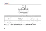
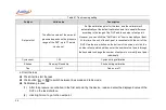
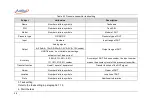
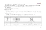
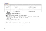
Table 16 Ramp Output Settings
Subject
Valid Value
Description
Range
Numbers
Ramp start and end value
Rise time
(1~999999)
Up stroke run time
Fall time
(1~999999)
Down stroke run time
High point dwell
(0~999999)
High point dwell time
Low point dwell
(0~999999)
low point dwell time
Cycle index
(
0~100
)
Ramp cycle index (a complete up and down stroke is a cycle), if
this item is set to 0, it means an infinite cycle.
Summary of Contents for 226
Page 1: ...226 227 Multifunction Process Calibrator...
Page 2: ......
Page 3: ...ADT226 227 Multifunction Process Calibrator User Manual Version 2306V01 Additel Corporation...
Page 4: ......
Page 6: ......
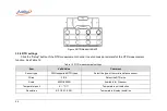
Page 31: ...19 1 4 Basic Structure Figure 1 Basic Structure...
Page 33: ...21 Figure 2 Power adaptor...
Page 64: ...52 External module information including external module A and external module B...
Page 107: ...95...


