2-10
Chapter2
SE6
1.
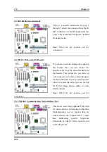
For using both two USB ports: Attach the optional
USB port expansion cable to connect Pin 1~ 10 on USB2
and USB3 slot.
2.
For using one USB port on CNR card: Attach a jumper
to short Pin 5 and 15, Pin 7 and 17. The additional USB
ports plug can be attached via USB3 (Pin 2, 4, 6, 8, 10, and Pin 12, 14, 16, 18, 20), but
there will be only one USB-port function available.
3.
For using one USB port on AGP card: Attach a jumper to short Pin 6 and 16, Pin 8 and 18.
The additional USB ports plug can be attached via USB2 (Pin 1, 3, 5, 7, 9 and Pin 11, 13,
15, 17, 19), but there will be only one USB-port function available.
(9) VL1 Connector
This connector is used for inserting an
optional add-on card to enable the on board
VGA to be output to TV-Out or Flat Panel.
(10) CDIN1: Internal CD-ROM Drive Audio Cable Header
This header is for the internal CD-ROM
drive audio cable connection. Please check
your audio cable attached with the CD-
ROM drive to see which type of connector
you have and then plug it into this header.
12 14 16 18 20
USB3
2
4
6
8 10
1
3
5
7
9
USB2
11
13 15 17 19
Summary of Contents for SE6
Page 2: ......
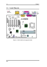
Page 8: ...1 4 Chapter1 SE6 1 3 Layout Diagram Figure 1 1 SE6 Motherboard component location ...
Page 10: ...1 6 Chapter1 SE6 ...
Page 80: ...3 50 Chapter3 SE6 ...
Page 92: ...C 4 Appendix C SE6 ...
Page 96: ...D 4 Appendix D SE6 ...
Page 104: ...Appendix F SE6 F 4 ...
Page 118: ...Appendix I SE6 I 6 ...
Page 126: ...Appendix K SE6 K 4 ...
Page 138: ...N 4 Appendix N SE6 ...
Page 144: ...O 6 Appendix O SE6 ...

