


2-14
Chapter2
SE6
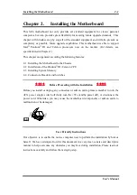
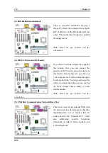
PN2 (Pin 1-2): Hardware Reset Switch Header
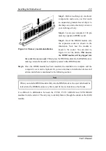
Attach the cable from the case’s front panel
reset switch to this header. Press and hold
the reset button for at least one second to
reset the system.
PN2 (Pin 4-5-6-7): Speaker Header
Attach the cable from the system speaker to
this header.
PN2 (Pin 9-10): Suspend LED Header
Insert the two-threaded suspend LED cable
into pin 9 and pin 10. If you install it in the
wrong direction, the LED light will not
illuminate correctly.
Note:
Watch the Suspend LED pin position
and the orientation.
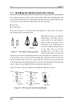
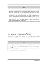
Table 2-3. PN1 and PN2 pin count name list
PIN Name
Significance of signal
PIN Name
Significance of signal
PIN 1
+5VDC
PIN 1
Ground
PIN 2
No connection
PIN 2
Reset input
PIN 3
Ground
PIN 3
Empty Pin
PIN 4
No Connection
PIN 4
No Connection
PIN 5
No Connection
PIN 5
+5 VDC
PIN6
Empty Pin
PIN6
Ground
PIN 7
LED Power
PIN 7
Ground
PIN 8
HDD active
PIN 8
Empty Pin
PIN 9
Empty Pin
PIN 9
Speaker Data
PIN 10 Ground
PIN 10 No Connection
PIN 11 Power On/Off
PIN 11 Empty Pin
PIN 12 Empty Pin
PIN 12 No connection
PIN 13 Ground
PIN 13 No connection
PN1
PIN 14 Suspend signal
PN2
PIN 14 No connection
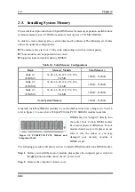
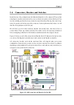
Let’s now see the I/O connectors that the SE6 uses, and what their functions are.
Summary of Contents for SE6
Page 2: ......
Page 8: ...1 4 Chapter1 SE6 1 3 Layout Diagram Figure 1 1 SE6 Motherboard component location ...
Page 10: ...1 6 Chapter1 SE6 ...
Page 80: ...3 50 Chapter3 SE6 ...
Page 92: ...C 4 Appendix C SE6 ...
Page 96: ...D 4 Appendix D SE6 ...
Page 104: ...Appendix F SE6 F 4 ...
Page 118: ...Appendix I SE6 I 6 ...
Page 126: ...Appendix K SE6 K 4 ...
Page 138: ...N 4 Appendix N SE6 ...
Page 144: ...O 6 Appendix O SE6 ...