


Installing the Motherboard
2-15
User’s Manual
(15) FDC1 Connector
This 34-pin connector is called the “
floppy
disk drive connector
”. You can connect a
360K, 5.25”, 1.2M, 5.25”, 720K, 3.5’’,
1.44M, 3.5” or 2.88M, 3.5” floppy disk
drive. You can even connect a 3 Mode
floppy disk drive (a 3 1/2” drive used in
Japanese computer systems).
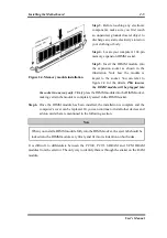
A floppy disk drive ribbon cable has 34
wires and two connectors to provide the
connection of two floppy disk drives. After
connecting the single end to the FDC1, connect the two connectors on the other end to the
floppy disk drives. In general, people only install one floppy disk drive on their computer
system. The end attached to the longer length of ribbon should be attached to the
motherboard connector.
Note
A red mark on a wire typically designates the location of pin 1. You need to align pin 1
of the wire to pin 1 of the FDC1 connector and then insert.
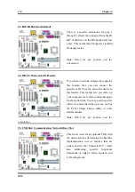
(16) IDE1 and IDE2 Connectors
An IDE hard disk drive ribbon cable has 40
wires and two connectors to provide a
connection for two IDE hard disk drives.
After connecting the single end to the IDE1
(or IDE2), connect the two connectors on
the other end to the IDE hard disk drives (or
CD-ROM drive, LS-120, etc.). Again the
connector attached to the longer ribbon
length should be attached to the
motherboard.
Before you install a hard disk, there are some things you need to be aware of:
♦
“Primary” refers to the first connector on the motherboard; that is, the IDE1 connector on
the motherboard.
Summary of Contents for SE6
Page 2: ......
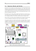
Page 8: ...1 4 Chapter1 SE6 1 3 Layout Diagram Figure 1 1 SE6 Motherboard component location ...
Page 10: ...1 6 Chapter1 SE6 ...
Page 80: ...3 50 Chapter3 SE6 ...
Page 92: ...C 4 Appendix C SE6 ...
Page 96: ...D 4 Appendix D SE6 ...
Page 104: ...Appendix F SE6 F 4 ...
Page 118: ...Appendix I SE6 I 6 ...
Page 126: ...Appendix K SE6 K 4 ...
Page 138: ...N 4 Appendix N SE6 ...
Page 144: ...O 6 Appendix O SE6 ...