


Installing the Motherboard
2-7
User’s Manual
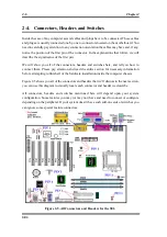
First, Let’s look at the headers that the SE6 uses, and what their functions are.
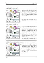
(1) ATXPR1: ATX Power Input Connector
Caution
If the power supply connectors are not properly attached to the ATXPR1 power supply,
the power supply or add-on cards may be damaged.
Attach the connector from the power supply
to the ATXPR1 connector here. Remember
you have to push the connector from the
ATX power supply firmly into the ATXPR1
connector, ensuring that you have a good
connection.
Note:
Watch the pin position and the
orientation
(2A)/(2B)/(2C): FAN1, FAN2 & FAN3 header
Attach the connector from the individual
CPU fan to the header named FAN1. The
connector from the chassis fan should be
attached to the header FAN3 and the
connector from the power fan to FAN2.
You must attach the CPU fan to the
processor or your processor will work
abnormally or may be damaged by
overheating. To keep the computer’s
internal temperature steady and not too high,
connecting the chassis fan is imperative.
Note:
Watch the pin position and the orientation
Summary of Contents for SE6
Page 2: ......
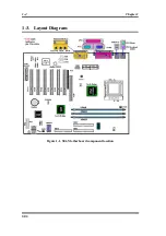
Page 8: ...1 4 Chapter1 SE6 1 3 Layout Diagram Figure 1 1 SE6 Motherboard component location ...
Page 10: ...1 6 Chapter1 SE6 ...
Page 80: ...3 50 Chapter3 SE6 ...
Page 92: ...C 4 Appendix C SE6 ...
Page 96: ...D 4 Appendix D SE6 ...
Page 104: ...Appendix F SE6 F 4 ...
Page 118: ...Appendix I SE6 I 6 ...
Page 126: ...Appendix K SE6 K 4 ...
Page 138: ...N 4 Appendix N SE6 ...
Page 144: ...O 6 Appendix O SE6 ...