Introduction of SE6 Features
1-1
User’s Manual
Chapter 1.
Introduction of SE6 Features
1-1. Features of This Motherboard
The SE6 Motherboard is designed for use with Intel’s new generation of Pentium Processors,
which utilize the FC-PGA (Plastic Pin Grid Array), 370-pin design. Up to 512MB of
memory can be supported.
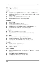
The SE6 uses the new Intel 815E chipset. Its’ 133 MHz capable memory interface supports
the wide range of PC 133 memory devices now on the market. Its 133MHz capable front-
side bus delivers a clear upgrade path to the future generation of 133MHz processors. The
SE6 offers Ultra ATA/100. This provides speedier HDD throughput that boosts overall
system performance. Up to four IDE devices can be supported by your system. These can be
either Ultra ATA/33 IDE devices, Ultra ATA/66 IDE devices or Ultra ATA/100 IDE devices.
A Digital Video Out Interface supporting digital display and TV Out are options. The SE6
also has an integrated AC’97 2.1 CODEC onboard. This CODEC is complete with a H/W
Sound Blaster Pro
AC’97 digital audio controller that gives you the best sound quality and
compatibility. The chipset includes integrated 2X 3D Graphics Acceleration. For those
wanting even greater graphics performance, an AGP slot is included on the board. The AGP
Slot will support a 4MB display cache AGP In-line Memory Module (AIMM). AIMM is a
lower cost alternative to a video card.
With 2 USB ports as well as capability of expanding to 4 USB slots, the SE6 meets future
USB demands. A Communication / Network Riser Slot (CNR Slot) is found on the SE6. The
CNR Slot provides audio, modem and network connectivity. The specification’s main
objective is to reduce the cost of audio and modem functionality.
The SE6 has built-in hardware monitoring functions (refer to
Appendix M
for detailed
information). This will monitor and protect your computer, ensuring a safe computing
environment.
This motherboard provides high performance for servers while also meeting the
requirements for desktop systems; both now and into the future.
Summary of Contents for SE6
Page 2: ......
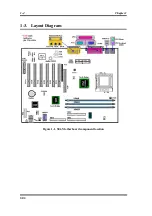
Page 8: ...1 4 Chapter1 SE6 1 3 Layout Diagram Figure 1 1 SE6 Motherboard component location ...
Page 10: ...1 6 Chapter1 SE6 ...
Page 80: ...3 50 Chapter3 SE6 ...
Page 92: ...C 4 Appendix C SE6 ...
Page 96: ...D 4 Appendix D SE6 ...
Page 104: ...Appendix F SE6 F 4 ...
Page 118: ...Appendix I SE6 I 6 ...
Page 126: ...Appendix K SE6 K 4 ...
Page 138: ...N 4 Appendix N SE6 ...
Page 144: ...O 6 Appendix O SE6 ...


