


Installing the Motherboard
2-9
User’s Manual
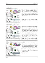
(6) SMB1 & SMB2 header: System Management Bus Connector
This connector is reserved for system
management bus (SM bus). The SM bus is a
specific implementation of an I
2
C bus. I
2
C is
a multi-master bus, which means that
multiple chips can be connected to the same
bus and each one can act as a master by
initiating a data transfer. If more than one
master simultaneously tries to control the
bus, an arbitration procedure decides which
master gets priority.
Note:
Watch the pin position and the orientation.
(7) RT2 Thermister:
The RT2 is a thermistor used to detect the
system environmental temperature. It may
also be called a system temperature detector.
You can attach one end of the two-threaded
thermal cable that comes with the
motherboard to the RT2 header, then tape
the other end of the thermal cable on the
CPU’s heat sink. Generally speaking, the
location you tape the thermistor should be as
near the CPU chipset as possible and avoid
having it near the CPU fan.
(8) USB2/3 Headers: Additional USB Plugs:
These headers are used for connecting the
additional USB ports plug. By attaching an
optional USB port expansion cable, you can
be provided with two additional USB plugs
affixed to the back panel.
There are three ways to use this additional
USB port:
Summary of Contents for SE6
Page 2: ......
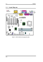
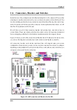
Page 8: ...1 4 Chapter1 SE6 1 3 Layout Diagram Figure 1 1 SE6 Motherboard component location ...
Page 10: ...1 6 Chapter1 SE6 ...
Page 80: ...3 50 Chapter3 SE6 ...
Page 92: ...C 4 Appendix C SE6 ...
Page 96: ...D 4 Appendix D SE6 ...
Page 104: ...Appendix F SE6 F 4 ...
Page 118: ...Appendix I SE6 I 6 ...
Page 126: ...Appendix K SE6 K 4 ...
Page 138: ...N 4 Appendix N SE6 ...
Page 144: ...O 6 Appendix O SE6 ...