2-8
Chapter2
SE6
(3)
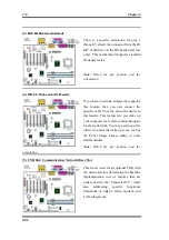
IR1: IR Header (Infrared)
There is a specific orientation for pins 1
through 5, attach the connector from the IR
KIT or IR device to the IR1 header (left row
only). This motherboard supports standard
IR transfer rates.
Note:
Watch the pin position and the
orientation
(4) WOL1: Wake on LAN Header
If you have a network adapter that supports
this feature, then you can connect the
specific cable from the network adapter to
this header.
This feature lets you wake up
your computer via remote control through a
local area network. You may need a specific
utility to control the wake up event, such as
the PCnet Magic Packet utility or other
similar utilities.
Note:
Watch the pin position and the
orientation
(5) CNR Slot: Communication Network Riser Slot
This slot is used for an optional CNR with
the main objective of reducing the baseline
implementation cost of features that are
widely used in the “Connected PC”, while
also addressing specific functional
limitations of today’s audio, modem, and
LAN subsystems.
Summary of Contents for SE6
Page 2: ......
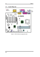
Page 8: ...1 4 Chapter1 SE6 1 3 Layout Diagram Figure 1 1 SE6 Motherboard component location ...
Page 10: ...1 6 Chapter1 SE6 ...
Page 80: ...3 50 Chapter3 SE6 ...
Page 92: ...C 4 Appendix C SE6 ...
Page 96: ...D 4 Appendix D SE6 ...
Page 104: ...Appendix F SE6 F 4 ...
Page 118: ...Appendix I SE6 I 6 ...
Page 126: ...Appendix K SE6 K 4 ...
Page 138: ...N 4 Appendix N SE6 ...
Page 144: ...O 6 Appendix O SE6 ...


