56
Tru O N E® AT S , I N S TA LL ATI O N A N D O PER ATI N G I N S TR U C TI O N
1
TO
U
C
H
—
4.2 Level 4 (touch) control interface, menu tree
Description of the icons
Password
—
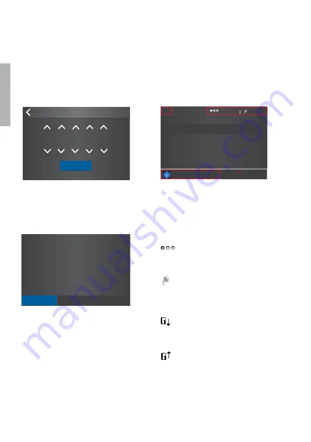
Fig. 4.8
Enter the password when asked, choose the
right number by arrowheads and confirm, go
forward entering number after number
—
Fig. 4.9
After you have changed the parameter, go back in the
menu by pressing the < on the top left corner or Home key
and when prompted confirm changes by Confirm option’
—
Fig. 4.10
The location of the small icons and the alarms
S1 Connected to Load
Load Current
393 A
11:06
60s
G
Override S1 Fail
TruONE ATS
System Overview
S1
Ok Not Ok
S2
—
Fig. 4.10
The default password is 00001, enter the
password when prompted (see Fig. 4.1).
Password
Confirm
0
* * * *
—
Fig. 4.8
—
Fig. 4.9
Programming
Application
2 Transformers/S1 Priority
Confirm
Abort
Modify
The small icons in System Overview
-pages are:
On upper right corner
Indicates the amount of pages
and the page where you are at
the moment
Auxiliary voltage connected
11:06 Time
Application set up as Transformer-
Generator. Generator start-up
signal deactivated
Application set up as Transformer-
Generator. Generator start-up
signal activated
On upper left corner
60s
Time delay, in Alarm list you can
see the name of delay at the
same time, e.g. Override S1 Fail
Summary of Contents for TruONE ATS
Page 2: ......
Page 6: ...6 TruONE ATS INSTALL ATION AND OPER ATING INSTRUCTION 1 ...
Page 151: ... Notes ...
Page 152: ... Notes ...
Page 153: ... Notes ...
Page 154: ... Notes ...
Page 155: ... Notes ...
Page 156: ... Notes ...
Page 157: ... Notes ...
Page 159: ......


