


II K 4-52
Overview of Software
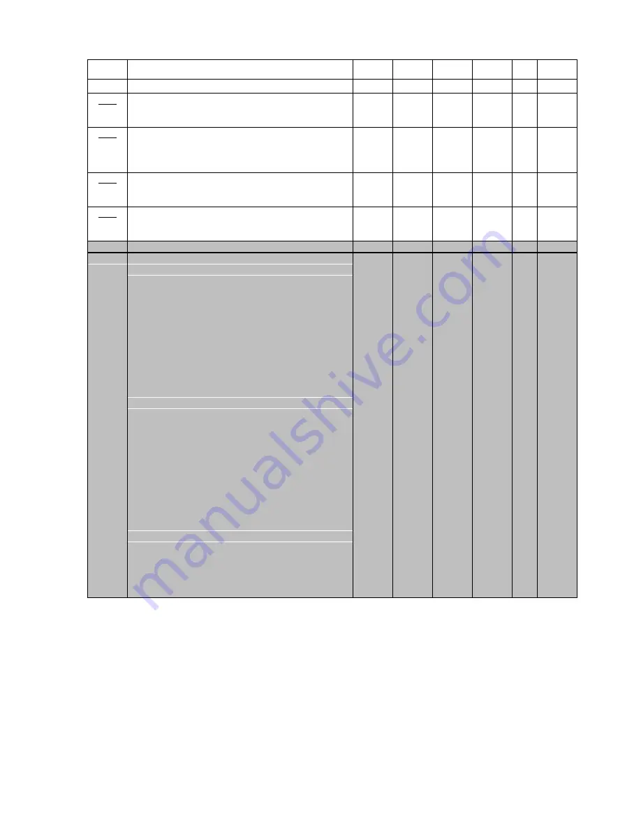
ParNo.
Parameter name and significance
Min
Max
Default
Unit
(1)
custom.
setting
Grp 3
Armature (continued)
3.10
auto-
tuning
Arm Cur Reg TI
Integration time constant of the armature current
controller (PI controller) in milliseconds.
0.0
1000.0
50.0
ms
3.11
auto-
tuning
Cont Cur Lim
Armature current value at the limit between
intermittent and continuous current in % related to
the nominal motor current (1.01)
0
100
50
%
3.12
auto-
tuning
Arm Inductance
Armature circuit inductance in millihenries.
0.00
655.35
0.00
mH
x
3.13
auto-
tuning
Arm Resistance
Armature circuit resistance in milliohms.
0
65535
0
mOhm
x
Long Parameter Menu
3.14
Cur Contr Mode
0 = Macro depend
The operating mode is defined
by macro, see macro descript.
1 = Speed Contr
Speed control
2 = Torque Contr
Torque control
3 = Cur Contr
Current control
4 = Speed+Torque
Speed + torque, both
reference values are added
5 = Lim SP Ctr
Speed control with external
torque limitation. That speed
reference via AI1 can be
limited externally via AI2 in its
torque. The torque limitation is
sign-independent.
6 = Lim Trq Ctr
Torque control with speed
limitation (window control
mode) for master-slave
applications. Master and slave
receive the same speed
reference. The slave has its
own speed feedback (tacho-
generator / encoder), but is
working in the current or
torque control mode. If the
speed deviation (reference /
actual value) > ±50 rpm, there
will be an automatic
changeover to speed control
until the deviation is corrected.
Then this mode will be
resumed.
0
6
0
Text
x
(1) no changes possible if the drive is in ON-status
Summary of Contents for DCS 400
Page 24: ...II K 3 14 Technical data ...
Page 29: ...II K 4 5 Overview of Software ...
Page 158: ...II K 6 36 Operating Instructions ...
Page 181: ...II K B 1 Appendix B Declaration of conformity ...
Page 190: ...Notices ...
Page 191: ...Notices ...


