II K 4-33
Overview of Software
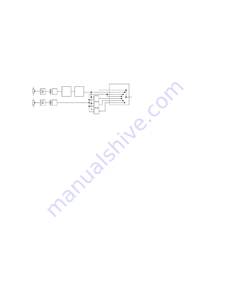
Armature current controller operating modes
The speed of a DC motor is altered with the armature
voltage. The range up to the point where the rated
armature voltage is reached is referred to as the
armature operating range
. To enable the motor’s
speed to be increased above these rated armature
voltage, the field’s magnetic flux has to be reduced.
This is done by reducing the field current. This oper-
ating range is referred to as the
field weakening
range
. The behavior of the current controller in these
operating ranges is depend on current controller
operating mode.
Macro depend
Speed Contr
Torque Contr
Cur Contr
Speed+Torque
Lim Sp Ctr
Lim Trq Ctr
&XU&WUO0RGH
Speed Ref
+/-10V
ext. Torque
Limitation
+/-10V
AI1
AI2
5.01
5.26
+
MIN
Σ
effective as Torque or Current
reference, depends on
Cur Ctrl Mode (3.14)
Ramp
Generator
Speed
Controller
Cur Ctrl Mode (3.14)
0 = Macro depend
The operation mode is defined by macro, see
chapter 4.1 Overview of factory settings of macro-
depent parameters.
Macro 1…7
are speed controlled, ref. to
1
Macro 8
is torque controlled, ref. to
2
1 = Speed Contr
Drive is speed controlled.
Always selects the output of the speed controller
as the torque reference in consideration of the flux.
During this mode current or torque limitaions are
effective as defined by parameter.
Stop
and
Emer-
gency Stop
are working as defined by parameter
Stop Mode (2.03)
and
Eme Stop Mode (2.04)
.
2 = Torque Contr
Drive is torque controlled.
Use the reference selected in
Torque Ref Sel
(3.15)
as the torque reference in consideration of
the flux. During this mode current or torque limi-
taions are effective as defined by parameter.
Stop
and
Emergency Stop
switchs the drive over to
speed controlled and works as defined by param-
eter
Stop Mode (2.03)
and
Eme Stop Mode
(2.04)
.
3 = Cur Contr
Drive is current controlled.
Use the reference selected in
Torque Ref Sel
(3.15)
as the
current
reference disregarding the
flux. During this mode current or torque limitaions
are effective as defined by parameter.
Stop
and
Emergency Stop
switchs the drive over to speed
controlled and works as defined by parameter
Stop Mode (2.03)
and
Eme Stop Mode (2.04)
.
4 = Speed + Torque („+“)
In this mode the speed controller output and the
reference selected in
Torque Ref Sel (3.15)
are
added. During this mode current or torque limi-
taions are effective as defined by parameter.
Stop
and
Emergency Stop
switchs the drive over to
speed controlled and works as defined by param-
eter
Stop Mode (2.03)
and
Eme Stop Mode
(2.04)
.
5 = Lim Sp Ctr („MIN“)
Lim
ited
Sp
eed
C
on
tr
ol. Drive is speed controlled
with external torque limitation.
Use the reference selected in
Torque Ref Sel
(3.15)
for limiting the torque in speed control mode.
During this mode current or torque limitaions are
effective as defined by parameter.
Stop
and
Emer-
gency Stop
switchs the drive over to speed con-
trolled and works as defined by parameter
Stop
Mode (2.03)
and
Eme Stop Mode (2.04)
.
6 = Lim Trq Ctr („
S
“)
Lim
ited
T
o
rq
ue
C
on
tr
ol. Drive is torque controlled
as long as the speed deviation remains within the
window. Flying alternation between speed and
torque control depend on speed deviation. Use the
reference selected in
Torque Ref Sel (3.15)
as the
torque reference. During this mode current or
torque limitaions are effective as defined by pa-
rameter.
Stop
and
Emergency Stop
switchs the
drive over to speed controlled and works as de-
fined by parameter
Stop Mode (2.03)
and
Eme
Stop Mode (2.04)
.
Summary of Contents for DCS 400
Page 24: ...II K 3 14 Technical data ...
Page 29: ...II K 4 5 Overview of Software ...
Page 158: ...II K 6 36 Operating Instructions ...
Page 181: ...II K B 1 Appendix B Declaration of conformity ...
Page 190: ...Notices ...
Page 191: ...Notices ...


