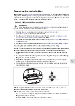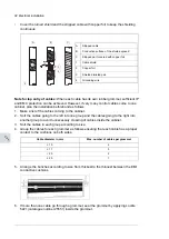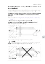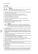
Connecting the input power cables
■
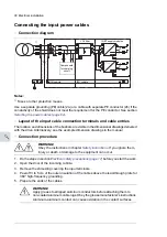
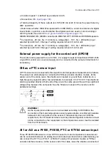
Connection diagram
1)
2a)
2b)
LCL filter
IGBT supply modules
Components
for charging
circuit
ISU cubicle
ICU cubicle
Notes:
1)
Fuses or other protection means.
Use a separate grounding (PE) cable (2a) or a cable with separate PE conductor (2b) if the
conductivity of the shield does not meet the requirement for the PE conductor. See section
Selecting the power cables (page 62)
■
Layout of the input cable connection terminals and cable entries
The location and dimensions of the busbars are visible in the dimensional drawings delivered
with the drive. Alternatively, see the example dimension drawings in the manual.
■
Connection procedure
WARNING!
Obey the instructions in chapter
. If you ignore them,
injury or death, or damage to the equipment can occur.
1.
Do the steps in section
Electrical safety precautions (page 17)
before you start the work.
2.
Open the door of the incoming cubicle.
3.
Remove the shrouding covering the input terminals.
4.
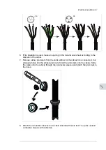
Peel off 3 to 5 cm of the outer insulation of the cables above the lead-through plate for
360° high-frequency grounding.
5.
Prepare the ends of the cables.
WARNING!
Apply grease to stripped aluminum conductors before attaching them to
non-coated aluminum cable lugs. Obey the grease manufacturer's instructions.
Aluminum-aluminum contact can cause oxidation in the contact surfaces.
90 Electrical installation
Summary of Contents for ACS880-37LC
Page 1: ... ABB INDUSTRIAL DRIVES ACS880 37LC drives Hardware manual ...
Page 2: ......
Page 4: ......
Page 78: ...78 ...
Page 116: ...116 ...
Page 134: ...5 Set the real time clock 134 Maintenance ...
Page 144: ...144 ...
Page 167: ... Dimension drawing examples ACS880 37LC 0390A 7 with main contactor Dimensions 167 ...
Page 169: ...ACS880 37LC 1270A 7 with common motor terminal cubicle Dimensions 169 ...
Page 170: ...ACS880 37LC 1940A 7 with common motor terminal cubicle 170 Dimensions ...
Page 172: ...Location and size of input terminals Contact ABB for details 172 Dimensions ...
Page 174: ...Inverter module cubicle with two R8i modules bottom cable exit 174 Dimensions ...
Page 175: ...Inverter module cubicle with three R8i modules bottom cable exit Dimensions 175 ...
Page 176: ...Brake chopper cubicle D150 176 Dimensions ...
Page 178: ...Cubicle width 300 mm top cable exit 178 Dimensions ...
Page 179: ...Cubicle width 400 mm bottom cable exit Dimensions 179 ...
Page 180: ...Cubicle width 400 mm top cable exit 180 Dimensions ...
Page 181: ...Cubicle width 600 mm bottom cable exit Dimensions 181 ...
Page 182: ...Cubicle width 600 mm top cable exit 182 Dimensions ...
Page 198: ...198 ...
Page 200: ...200 ...

