Description
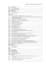
Code
Terminals for connecting external control voltage (230 V AC or 115 V AC, eg. UPS). See section
Descriptions of options (page 32)
.
G307
Output for motor space heater (external supply)
G313
Aluminum busbars (standard up to 3200 A)
G314
Tin-plated copper busbars (optional up to 3200 A, standard from 3200 A up)
G315
Cable supply conductors
G316
Control (auxiliary) voltage 230 V AC
G320
Halogen-free wiring and materials
G330
Electrical disconnect push button on the door (black, opens main contactor / ACB)
G332
kW-meter on door
G333
V-meter with selector switch
G334
A-meter in one phase
G335
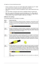
Additional wire markings. See section
Descriptions of options (page 32)
.
G338
G339
G340
G341
G342
Auxiliary voltage transformer
G344
Frequency monitoring device. Only for installation altitudes up to 2000 meters (6561 ft).
G432
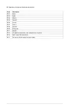
Cabling
Motor cabling direction up
H353
Common motor terminal cubicle. See section
Descriptions of options (page 32)
H359
Gland plate out of 3 mm thick aluminum, blind
H364
Control cable entry through floor of cabinet
H367
Control panel
ACS-AP-W control panel (with Bluetooth)
J400
Fieldbus adapters, diverse communication options
FDNA-01 DeviceNet™ adapter module
K451
FLON-01 LonWorks
®
adapter module
K452
FPBA-01 PROFIBUS DP adapter module
K454
FCAN-01 CANopen adapter module
K457
FSCA-01 RS-485 (Modbus/RTU) adapter module
K458
FCNA-01 ControlNet™ adapter module
K462
FECA-01 EtherCat adapter module
K469
FEPL-02 EtherPOWERLINK adapter module
K470
FENA-11 Ethernet adapter module for EtherNet/IP™, Modbus TCP and PROFINET IO protocols
K473
FENA-21 Ethernet adapter module for EtherNet/IP™, Modbus TCP and PROFINET IO protocols,
2-port
K475
I/O extensions and feedback interfaces
FIO-11 analog I/O extension module (1, 2 or 3 pcs)
L500
FIO-01 digital I/O extension module (1, 2 or 3 pcs)
L501
FEN-31 HTL incremental encoder interface module
L502
Thermal protection with PTC relays (1 or 2 pcs). See section
Descriptions of options (page 32)
L505
38 Operation principle and hardware description
Summary of Contents for ACS880-37LC
Page 1: ... ABB INDUSTRIAL DRIVES ACS880 37LC drives Hardware manual ...
Page 2: ......
Page 4: ......
Page 78: ...78 ...
Page 116: ...116 ...
Page 134: ...5 Set the real time clock 134 Maintenance ...
Page 144: ...144 ...
Page 167: ... Dimension drawing examples ACS880 37LC 0390A 7 with main contactor Dimensions 167 ...
Page 169: ...ACS880 37LC 1270A 7 with common motor terminal cubicle Dimensions 169 ...
Page 170: ...ACS880 37LC 1940A 7 with common motor terminal cubicle 170 Dimensions ...
Page 172: ...Location and size of input terminals Contact ABB for details 172 Dimensions ...
Page 174: ...Inverter module cubicle with two R8i modules bottom cable exit 174 Dimensions ...
Page 175: ...Inverter module cubicle with three R8i modules bottom cable exit Dimensions 175 ...
Page 176: ...Brake chopper cubicle D150 176 Dimensions ...
Page 178: ...Cubicle width 300 mm top cable exit 178 Dimensions ...
Page 179: ...Cubicle width 400 mm bottom cable exit Dimensions 179 ...
Page 180: ...Cubicle width 400 mm top cable exit 180 Dimensions ...
Page 181: ...Cubicle width 600 mm bottom cable exit Dimensions 181 ...
Page 182: ...Cubicle width 600 mm top cable exit 182 Dimensions ...
Page 198: ...198 ...
Page 200: ...200 ...


