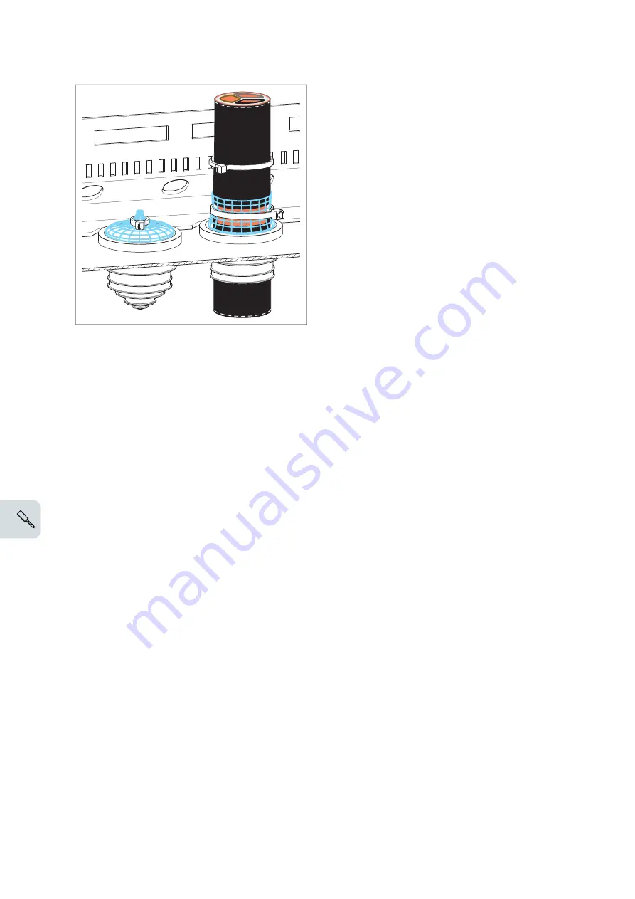
9.
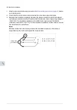
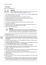
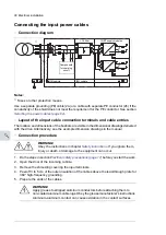
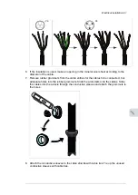
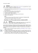
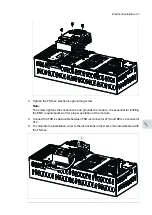
Seal the gap between the cable and mineral wool sheet (if used) with sealing compound
(eg. CSD-F, ABB brand name DXXT-11, code 35080082).
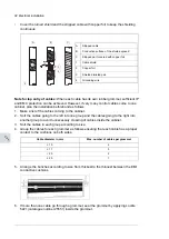
10. Connect the twisted shields of the cables to the PE busbar of the cabinet.
11. Connect the phase conductors of the input cable to the L1, L2 and L3 terminals. Tighten
the screws to the torque given under
.
12. Reinstall the shrouding removed earlier.
13. Close the cubicle door.
92 Electrical installation
Summary of Contents for ACS880-37LC
Page 1: ... ABB INDUSTRIAL DRIVES ACS880 37LC drives Hardware manual ...
Page 2: ......
Page 4: ......
Page 78: ...78 ...
Page 116: ...116 ...
Page 134: ...5 Set the real time clock 134 Maintenance ...
Page 144: ...144 ...
Page 167: ... Dimension drawing examples ACS880 37LC 0390A 7 with main contactor Dimensions 167 ...
Page 169: ...ACS880 37LC 1270A 7 with common motor terminal cubicle Dimensions 169 ...
Page 170: ...ACS880 37LC 1940A 7 with common motor terminal cubicle 170 Dimensions ...
Page 172: ...Location and size of input terminals Contact ABB for details 172 Dimensions ...
Page 174: ...Inverter module cubicle with two R8i modules bottom cable exit 174 Dimensions ...
Page 175: ...Inverter module cubicle with three R8i modules bottom cable exit Dimensions 175 ...
Page 176: ...Brake chopper cubicle D150 176 Dimensions ...
Page 178: ...Cubicle width 300 mm top cable exit 178 Dimensions ...
Page 179: ...Cubicle width 400 mm bottom cable exit Dimensions 179 ...
Page 180: ...Cubicle width 400 mm top cable exit 180 Dimensions ...
Page 181: ...Cubicle width 600 mm bottom cable exit Dimensions 181 ...
Page 182: ...Cubicle width 600 mm top cable exit 182 Dimensions ...
Page 198: ...198 ...
Page 200: ...200 ...

