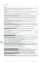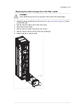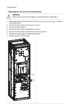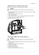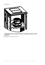
Action
Check that the main switch-disconnector (Q1.1) is switched off, or main breaker (Q1) racked out.
Check the mechanical and electrical installation of the drive. See
.
Check the settings of breakers/switches in the auxiliary circuits. See the circuit diagrams delivered with
the drive.
Check the settings of the auxiliary voltage transformers (either internal or external).
Disconnect any unfinished or uninspected auxiliary voltage (115/230 V AC) cables that lead from the
terminal blocks to the outside of the equipment.
Check that both channels of the Safe torque off circuit connected to the STO inputs of both the supply
control unit [A51] and the inverter control unit [A41] are closed. Refer to the wiring diagrams delivered
with the drive.
If the Safe torque off functionality is used, check that the STO OUT output on the inverter control unit
(A41) is chained to the STO inputs of all inverter modules.
If the Safe torque off functionality is not used, check that the STO input on all inverter modules is correctly
wired to +24 V and ground.
Powering up the auxiliary circuit of the drive
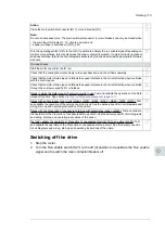
Make sure that it is safe to connect voltage. Ensure that
• nobody is working on the drive or circuits that have been wired from outside into the drive cabinet
• the cover of the motor terminal box is in place.
Drives with a voltmeter (G334): Make sure that the circuit breaker of the measuring circuit
(F5.1) is closed.
Close the circuit breakers and/or fuse disconnectors supplying the auxiliary voltage circuits.
Close the cabinet doors.
Close the main breaker of the supply transformer.
Switch on the auxiliary voltage [Q21].
Drives of frame size 1×R8i + 1×R8i: Close the main switch-disconnector [Q1.1]. This will power up the
main circuit of the drive as well as the auxiliary voltage circuit.
Setting up the supply unit parameters
Check the voltage range setting in parameter
195.01 Supply voltage
.
For more information on setting up the supply control program, see the
ACS880 IGBT supply control
program firmware manual
(3AUA0000131562 [English]).
If you need more information on the use of the control panel, see the
ACX-AP-x Assistant control
panels user's manual
(3AUA0000085685 [English]).
Setting up the inverter unit parameters, and performing the first start
Set up the inverter control program. See the appropriate start-up guide and/or firmware manual. There
is a separate start-up guide only for some control programs.
Check that parameter
95.09 Switch fuse controller
is set to
Disabled
.
Drives with a brake chopper (D150): See chapter
Drives with an fieldbus adapter module (optional): Set the fieldbus parameters. Activate the appropriate
assistant (if present) in the control program, or see the user’s manual of the fieldbus adapter module,
and the drive firmware manual. Check that the communication works between the drive and the PLC.
Drives with an encoder interface module (optional): Set the encoder parameters. Activate the appropriate
assistant (if present) in the control program, or see the user’s manual of the encoder interface module,
and the drive firmware manual.
Powering up the main circuit of the drive
114 Start-up
Summary of Contents for ACS880-37LC
Page 1: ... ABB INDUSTRIAL DRIVES ACS880 37LC drives Hardware manual ...
Page 2: ......
Page 4: ......
Page 78: ...78 ...
Page 116: ...116 ...
Page 134: ...5 Set the real time clock 134 Maintenance ...
Page 144: ...144 ...
Page 167: ... Dimension drawing examples ACS880 37LC 0390A 7 with main contactor Dimensions 167 ...
Page 169: ...ACS880 37LC 1270A 7 with common motor terminal cubicle Dimensions 169 ...
Page 170: ...ACS880 37LC 1940A 7 with common motor terminal cubicle 170 Dimensions ...
Page 172: ...Location and size of input terminals Contact ABB for details 172 Dimensions ...
Page 174: ...Inverter module cubicle with two R8i modules bottom cable exit 174 Dimensions ...
Page 175: ...Inverter module cubicle with three R8i modules bottom cable exit Dimensions 175 ...
Page 176: ...Brake chopper cubicle D150 176 Dimensions ...
Page 178: ...Cubicle width 300 mm top cable exit 178 Dimensions ...
Page 179: ...Cubicle width 400 mm bottom cable exit Dimensions 179 ...
Page 180: ...Cubicle width 400 mm top cable exit 180 Dimensions ...
Page 181: ...Cubicle width 600 mm bottom cable exit Dimensions 181 ...
Page 182: ...Cubicle width 600 mm top cable exit 182 Dimensions ...
Page 198: ...198 ...
Page 200: ...200 ...

