Installation checklist of the drive
Contents of this chapter
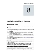
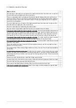
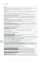
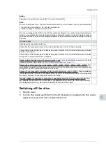
This chapter contains a checklist of the mechanical and electrical installation of the drive.
Checklist
Examine the mechanical and electrical installation of the drive before start-up. Go through
the checklist together with another person.
WARNING!
Obey the safety instructions of the drive. If you ignore them, injury or death, or
damage to the equipment can occur.
If you are not a qualified electrician, do not do installation or maintenance work.
WARNING!
Stop the drive and do the steps in section
Electrical safety precautions (page 17)
before you start the work.
Make sure that …
The ambient operating conditions meet the drive ambient conditions specification, and enclosure rating
(IP code or UL enclosure type).
The supply voltage matches the nominal input voltage of the drive. See the type designation label.
The drive cabinet has been attached to floor, and if necessary due to vibration etc, also by its top to
the wall or roof.
If the drive is connected to a network other than a symetrically grounded TN-S system: Check the
compatibility. See the electrical installation instructions.
There is an adequately sized protective earth (ground) conductor between the drive and the switchboard,
the conductor has been connected to appropriate terminal, and the terminal has been tightened to the
proper torque. Proper grounding has also been measured according to the regulations.
8
Installation checklist of the drive 111
Summary of Contents for ACS880-37LC
Page 1: ... ABB INDUSTRIAL DRIVES ACS880 37LC drives Hardware manual ...
Page 2: ......
Page 4: ......
Page 78: ...78 ...
Page 116: ...116 ...
Page 134: ...5 Set the real time clock 134 Maintenance ...
Page 144: ...144 ...
Page 167: ... Dimension drawing examples ACS880 37LC 0390A 7 with main contactor Dimensions 167 ...
Page 169: ...ACS880 37LC 1270A 7 with common motor terminal cubicle Dimensions 169 ...
Page 170: ...ACS880 37LC 1940A 7 with common motor terminal cubicle 170 Dimensions ...
Page 172: ...Location and size of input terminals Contact ABB for details 172 Dimensions ...
Page 174: ...Inverter module cubicle with two R8i modules bottom cable exit 174 Dimensions ...
Page 175: ...Inverter module cubicle with three R8i modules bottom cable exit Dimensions 175 ...
Page 176: ...Brake chopper cubicle D150 176 Dimensions ...
Page 178: ...Cubicle width 300 mm top cable exit 178 Dimensions ...
Page 179: ...Cubicle width 400 mm bottom cable exit Dimensions 179 ...
Page 180: ...Cubicle width 400 mm top cable exit 180 Dimensions ...
Page 181: ...Cubicle width 600 mm bottom cable exit Dimensions 181 ...
Page 182: ...Cubicle width 600 mm top cable exit 182 Dimensions ...
Page 198: ...198 ...
Page 200: ...200 ...

