Routing the cables
■
General guidelines, IEC
•
Route the motor cable away from other cables. Motor cables of several drives can be
run in parallel installed next to each other.
•
Install the motor cable, input power cable and control cables on separate trays.
•
Avoid long parallel runs of motor cables with other cables in order to decrease
electromagnetic interference caused by the rapid changes in the drive output voltage.
•
Where control cables must cross power cables, make sure they are arranged at an
angle as near to 90 degrees as possible.
•
Do not run extra cables through the drive.
•
Make sure that the cable trays have good electrical bonding to each other and to the
grounding electrodes. Aluminum tray systems can be used to improve local equalizing
of potential.
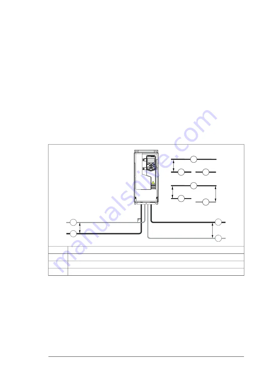
This figure illustrates the cable routing guidelines with an example drive.
min. 200 mm (8 in)
90°
*min. 500 mm (20 in)
1
2
3
3
2
1
4
min. 300 mm (12 in)
2
4
3
min. 300 mm (12 in)
*
Motor cable
1
Input power cable
2
Control cable
3
Brake resistor or chopper cable (if any)
4
■
Continuous motor cable shield or enclosure for equipment on the
motor cable
To minimize the emission level when safety switches, contactors, connection boxes or
similar equipment are installed on the motor cable between the drive and the motor:
•
Install the equipment in a metal enclosure.
•
Use either a symmetrical shielded cable (preferred alternative), or install the cabling in
a metal conduit.
•
Make sure that there is a good and continuous galvanic connection in the shield/conduit
between drive and motor.
•
Connect the shield/conduit to the protective ground terminal of the drive and the motor.
Guidelines for planning the electrical installation 67
Summary of Contents for ACS880-37LC
Page 1: ... ABB INDUSTRIAL DRIVES ACS880 37LC drives Hardware manual ...
Page 2: ......
Page 4: ......
Page 78: ...78 ...
Page 116: ...116 ...
Page 134: ...5 Set the real time clock 134 Maintenance ...
Page 144: ...144 ...
Page 167: ... Dimension drawing examples ACS880 37LC 0390A 7 with main contactor Dimensions 167 ...
Page 169: ...ACS880 37LC 1270A 7 with common motor terminal cubicle Dimensions 169 ...
Page 170: ...ACS880 37LC 1940A 7 with common motor terminal cubicle 170 Dimensions ...
Page 172: ...Location and size of input terminals Contact ABB for details 172 Dimensions ...
Page 174: ...Inverter module cubicle with two R8i modules bottom cable exit 174 Dimensions ...
Page 175: ...Inverter module cubicle with three R8i modules bottom cable exit Dimensions 175 ...
Page 176: ...Brake chopper cubicle D150 176 Dimensions ...
Page 178: ...Cubicle width 300 mm top cable exit 178 Dimensions ...
Page 179: ...Cubicle width 400 mm bottom cable exit Dimensions 179 ...
Page 180: ...Cubicle width 400 mm top cable exit 180 Dimensions ...
Page 181: ...Cubicle width 600 mm bottom cable exit Dimensions 181 ...
Page 182: ...Cubicle width 600 mm top cable exit 182 Dimensions ...
Page 198: ...198 ...
Page 200: ...200 ...


