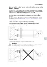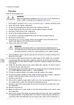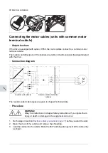
Connecting the control cables
See chapter
Control units of the drive (page 99)
for the default I/O connections of the inverter
unit (with the ACS880 primary control program). The default I/O connections can be different
with some hardware options, see the circuit diagrams delivered with the drive for the actual
wiring. For other control programs, see their firmware manuals.
■
Control cable connection procedure
WARNING!
Obey the instructions in chapter
. If you ignore them, injury or
death, or damage to the equipment can occur.
1.
Stop the drive (if running) and do the steps in section
before you start the work.
2.
Run the control cables into the cabinet as described in section
shields of the control cables at the cabinet entry
below.
3.
Route the control cables as described in section
Routing the control cables inside the
4.
Connect the control cables as described in section
Connecting control cabling (page 83)
Grounding the outer shields of the control cables at the cabinet entry
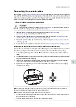
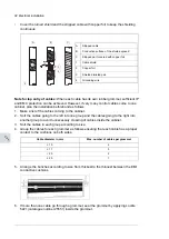
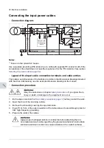
Ground the outer shields of all control cables 360 degrees at the EMI conductive cushions
as follows (example constructions are shown below, the actual hardware may vary):
1.
Loosen the tightening screws of the EMI conductive cushions and pull the cushions
apart.
2.
Cut adequate holes to the rubber grommets in the entry plate and put the cables through
the grommets and the cushions.
3.
Strip off the cable plastic sheath above the entry plate just enough to ensure proper
connection of the bare shield and the EMI conductive cushions.
4.
Tighten the two tightening screws so that the EMI conductive cushions press tightly
round the bare shield.
3
2
4
1
Note 1:
Keep the shields continuous as close to the connection terminals as possible.
Secure the cables mechanically at the entry strain relief.
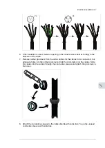
Note 2:
If the outer surface of the shield is non-conductive:
•
Cut the shield at the midpoint of the bare part. Be careful not to cut the conductors or
the grounding wire (if present).
•
Turn the shield inside out to expose its conductive surface.
Electrical installation 81
11
Summary of Contents for ACS880-37LC
Page 1: ... ABB INDUSTRIAL DRIVES ACS880 37LC drives Hardware manual ...
Page 2: ......
Page 4: ......
Page 78: ...78 ...
Page 116: ...116 ...
Page 134: ...5 Set the real time clock 134 Maintenance ...
Page 144: ...144 ...
Page 167: ... Dimension drawing examples ACS880 37LC 0390A 7 with main contactor Dimensions 167 ...
Page 169: ...ACS880 37LC 1270A 7 with common motor terminal cubicle Dimensions 169 ...
Page 170: ...ACS880 37LC 1940A 7 with common motor terminal cubicle 170 Dimensions ...
Page 172: ...Location and size of input terminals Contact ABB for details 172 Dimensions ...
Page 174: ...Inverter module cubicle with two R8i modules bottom cable exit 174 Dimensions ...
Page 175: ...Inverter module cubicle with three R8i modules bottom cable exit Dimensions 175 ...
Page 176: ...Brake chopper cubicle D150 176 Dimensions ...
Page 178: ...Cubicle width 300 mm top cable exit 178 Dimensions ...
Page 179: ...Cubicle width 400 mm bottom cable exit Dimensions 179 ...
Page 180: ...Cubicle width 400 mm top cable exit 180 Dimensions ...
Page 181: ...Cubicle width 600 mm bottom cable exit Dimensions 181 ...
Page 182: ...Cubicle width 600 mm top cable exit 182 Dimensions ...
Page 198: ...198 ...
Page 200: ...200 ...


