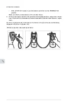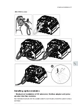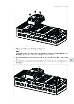
Routing the control cables inside the cabinet
Use the existing trunking in the cabinet wherever possible. Use sleeving if cables are laid
against sharp edges. When running cables to or from a swing-out frame, leave enough
slack at the hinge to allow the frame to open fully.
Connecting control cabling
Connect the conductors to the appropriate terminals. Refer to the wiring diagrams delivered
with the drive.
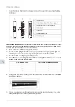
Connect the inner twisted pair shields and all separate grounding wires to the grounding
clamps closest to the terminals.
The drawing below represents the grounding of the control cabling when connecting to a
terminal block inside the cabinet. The grounding is done in the same way when connecting
directly to a component such as the control unit.
Notes:
•
Do not ground the outer shield of the cable here since it is grounded at the lead-through.
•
Keep any signal wire pairs twisted as close to the terminals as possible. Twisting the
wire with its return wire reduces disturbances caused by inductive coupling.
100 Electrical installation
At the other end of the cable, leave the shields unconnected or ground them indirectly via
a high-frequency capacitor with a few nanofarads, eg. 3.3 nF / 630 V. The shield can also
be grounded directly at both ends if they are in the same ground line with no significant
voltage drop between the end points.
Electrical installation 83
11
Summary of Contents for ACS880-37LC
Page 1: ... ABB INDUSTRIAL DRIVES ACS880 37LC drives Hardware manual ...
Page 2: ......
Page 4: ......
Page 78: ...78 ...
Page 116: ...116 ...
Page 134: ...5 Set the real time clock 134 Maintenance ...
Page 144: ...144 ...
Page 167: ... Dimension drawing examples ACS880 37LC 0390A 7 with main contactor Dimensions 167 ...
Page 169: ...ACS880 37LC 1270A 7 with common motor terminal cubicle Dimensions 169 ...
Page 170: ...ACS880 37LC 1940A 7 with common motor terminal cubicle 170 Dimensions ...
Page 172: ...Location and size of input terminals Contact ABB for details 172 Dimensions ...
Page 174: ...Inverter module cubicle with two R8i modules bottom cable exit 174 Dimensions ...
Page 175: ...Inverter module cubicle with three R8i modules bottom cable exit Dimensions 175 ...
Page 176: ...Brake chopper cubicle D150 176 Dimensions ...
Page 178: ...Cubicle width 300 mm top cable exit 178 Dimensions ...
Page 179: ...Cubicle width 400 mm bottom cable exit Dimensions 179 ...
Page 180: ...Cubicle width 400 mm top cable exit 180 Dimensions ...
Page 181: ...Cubicle width 600 mm bottom cable exit Dimensions 181 ...
Page 182: ...Cubicle width 600 mm top cable exit 182 Dimensions ...
Page 198: ...198 ...
Page 200: ...200 ...


