


clearly marked as defined in IEC/EN 61800-5-1, subclause 6.5.3, for example, “THIS
MACHINE STARTS AUTOMATICALLY”.
Bypass connection is available as a factory-installed option for some cabinet-installed drive
types. Consult ABB for more information.
WARNING!
Never connect the drive output to the electrical power network. The connection
may damage the drive.
■
Implementing the ATEX-certified Safe motor disconnection function
(Q971)
With Q971, the drive provides ATEX-certified safe motor disconnection without
contactor using the drive Safe torque off function. For more information, see
•
ATEX-certified Safe disconnection function, Ex II (2) GD for ACS880 drives (+Q971)
Application guide
(3AUA0000132231 [English]).
•
FPTC-02 ATEX-certified thermistor protection module, Ex II (2) GD (L537+Q971)
for ACS880 drives user's manual
(3AXD50000027782 [English]).
•
CPTC-02 ATEX-certified thermistor protection module, Ex II (2) GD (L537+Q971)
user's manual
(3AXD50000030058 [English]).
■
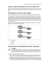
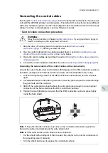
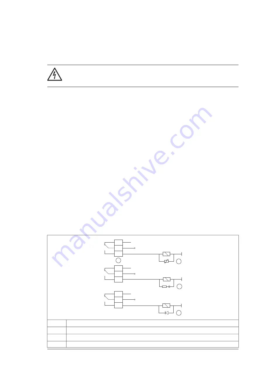
Protecting the contacts of relay outputs
Inductive loads (relays, contactors, motors) cause voltage transients when switched off.
The relay contacts on the drive control unit are protected with varistors (250 V) against
overvoltage peaks. In spite of this, it is highly recommended that inductive loads are equipped
with noise attenuating circuits (varistors, RC filters [AC] or diodes [DC]) to minimize the
EMC emission at switch-off. If not suppressed, the disturbances may connect capacitively
or inductively to other conductors in the control cable and form a risk of malfunction in other
parts of the system.
Install the protective component as close to the inductive load as possible. Do not install
protective components at the relay outputs.
2
3
4
230 V AC
230 V AC
+ 24 V DC
1
Relay output
1
Varistor
2
RC filter
3
Diode
4
Guidelines for planning the electrical installation 71
Summary of Contents for ACS880-37LC
Page 1: ... ABB INDUSTRIAL DRIVES ACS880 37LC drives Hardware manual ...
Page 2: ......
Page 4: ......
Page 78: ...78 ...
Page 116: ...116 ...
Page 134: ...5 Set the real time clock 134 Maintenance ...
Page 144: ...144 ...
Page 167: ... Dimension drawing examples ACS880 37LC 0390A 7 with main contactor Dimensions 167 ...
Page 169: ...ACS880 37LC 1270A 7 with common motor terminal cubicle Dimensions 169 ...
Page 170: ...ACS880 37LC 1940A 7 with common motor terminal cubicle 170 Dimensions ...
Page 172: ...Location and size of input terminals Contact ABB for details 172 Dimensions ...
Page 174: ...Inverter module cubicle with two R8i modules bottom cable exit 174 Dimensions ...
Page 175: ...Inverter module cubicle with three R8i modules bottom cable exit Dimensions 175 ...
Page 176: ...Brake chopper cubicle D150 176 Dimensions ...
Page 178: ...Cubicle width 300 mm top cable exit 178 Dimensions ...
Page 179: ...Cubicle width 400 mm bottom cable exit Dimensions 179 ...
Page 180: ...Cubicle width 400 mm top cable exit 180 Dimensions ...
Page 181: ...Cubicle width 600 mm bottom cable exit Dimensions 181 ...
Page 182: ...Cubicle width 600 mm top cable exit 182 Dimensions ...
Page 198: ...198 ...
Page 200: ...200 ...