


WARNING!
Obey the instructions in chapter
. If you ignore them, injury or
death, or damage to the equipment can occur.
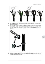
1.
Stop the drive and do the steps in section
Electrical safety precautions (page 17)
before
you start the work.
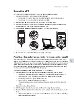
2.
Open the door of the auxiliary control cubicle (ACU).
3.
Remove the shrouding at the top of the cubicle.
4.
Locate the inverter control unit (A41).
5.
Insert the module carefully into its position on the control unit.
6.
Fasten the mounting screw.
Note:
The screw secures and grounds the module. It is essential for fulfilling the EMC
requirements and for proper operation of the module.
■
Installation of an FSO-xx safety functions module onto BCU
WARNING!
Obey the instructions in chapter Safety instructions. If you ignore them,
injury or death, or damage to the equipment can occur.
This procedure describes the installation of an FSO-xx safety functions module onto the
BCU control unit. (The FSO-xx can alternatively be installed beside the control unit, which
is the standard with factory-installed FSO-xx modules. For instructions, see the FSO-xx
manual.)
1.
Stop the inverter unit and do the steps in section
Electrical safety precautions (page 17)
before you start the work.
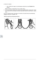
2.
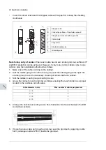
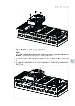
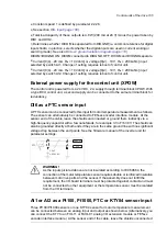
The FSO-xx comes with alternative bottom plates for mounting on different units. For
mounting on the BCU, the mounting points should be located at the long edges of the
module as shown. Replace the bottom plate of the FSO-xx if necessary.
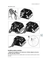
3.
Fasten the FSO-xx onto slot 3 of the BCU control unit [A41] with four screws.
96 Electrical installation
Summary of Contents for ACS880-37LC
Page 1: ... ABB INDUSTRIAL DRIVES ACS880 37LC drives Hardware manual ...
Page 2: ......
Page 4: ......
Page 78: ...78 ...
Page 116: ...116 ...
Page 134: ...5 Set the real time clock 134 Maintenance ...
Page 144: ...144 ...
Page 167: ... Dimension drawing examples ACS880 37LC 0390A 7 with main contactor Dimensions 167 ...
Page 169: ...ACS880 37LC 1270A 7 with common motor terminal cubicle Dimensions 169 ...
Page 170: ...ACS880 37LC 1940A 7 with common motor terminal cubicle 170 Dimensions ...
Page 172: ...Location and size of input terminals Contact ABB for details 172 Dimensions ...
Page 174: ...Inverter module cubicle with two R8i modules bottom cable exit 174 Dimensions ...
Page 175: ...Inverter module cubicle with three R8i modules bottom cable exit Dimensions 175 ...
Page 176: ...Brake chopper cubicle D150 176 Dimensions ...
Page 178: ...Cubicle width 300 mm top cable exit 178 Dimensions ...
Page 179: ...Cubicle width 400 mm bottom cable exit Dimensions 179 ...
Page 180: ...Cubicle width 400 mm top cable exit 180 Dimensions ...
Page 181: ...Cubicle width 600 mm bottom cable exit Dimensions 181 ...
Page 182: ...Cubicle width 600 mm top cable exit 182 Dimensions ...
Page 198: ...198 ...
Page 200: ...200 ...