Code
Name
3AUA0000119895
Emergency stop, stop category 0 (Q951) for ACS880-07/17/17LC/37/37LC drives
user's manual
3AUA0000119896
Emergency stop, stop category 1 (Q952) for ACS880-07/17/17LC/37/37LC drives
user's manual
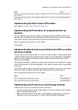
Implementing the Safe torque off function
See chapter
The Safe torque off function (page 183)
Implementing the Prevention of unexpected start-up
function
You can order the drive with a Prevention of unexpected start-up (POUS) function. The
POUS function enables short-time maintenance work (like cleaning) on the non-electrical
parts of the machinery without switching off and disconnecting the drive.
See the appropriate manual for more information.
TO BE ADDED
Implementing the functions provided by the FSO-xx safety
functions module
You can order the drive with an FSO-12 or FSO-21 safety functions module (Q972
or +Q973) which enables the implementation of functions such as Safe brake control (SBC),
Safe stop 1 (SS1), Safe stop emergency (SSE), Safely limited speed (SLS) and Safe
maximum speed (SMS).
The settings of the FSO-xx module are at default when delivered from the factory. The wiring
of the external safety circuit and configuration of the FSO-xx module are the responsibility
of the user.
The FSO-xx module reserves the standard Safe torque off (STO) connection of the inverter
control unit. STO can still be utilized by other safety circuits through the FSO-xx.
See the appropriate manual for more information.
Code
Name
3AXD50000015612
FSO-12 safety functions module user's manual
3AXD50000015614
FSO-21 safety functions module user's manual
Implementing the Power-loss ride-through function
Implement the power-loss ride-through function as follows:
•
Check that the power-loss ride-through function of the drive (inverter unit) is enabled.
See the drive firmware manual.
•
Make sure that the control of the main contactor/breaker either keeps the contactor
closed over the short power break, or closes it after the break automatically.
Guidelines for planning the electrical installation 73
Summary of Contents for ACS880-37LC
Page 1: ... ABB INDUSTRIAL DRIVES ACS880 37LC drives Hardware manual ...
Page 2: ......
Page 4: ......
Page 78: ...78 ...
Page 116: ...116 ...
Page 134: ...5 Set the real time clock 134 Maintenance ...
Page 144: ...144 ...
Page 167: ... Dimension drawing examples ACS880 37LC 0390A 7 with main contactor Dimensions 167 ...
Page 169: ...ACS880 37LC 1270A 7 with common motor terminal cubicle Dimensions 169 ...
Page 170: ...ACS880 37LC 1940A 7 with common motor terminal cubicle 170 Dimensions ...
Page 172: ...Location and size of input terminals Contact ABB for details 172 Dimensions ...
Page 174: ...Inverter module cubicle with two R8i modules bottom cable exit 174 Dimensions ...
Page 175: ...Inverter module cubicle with three R8i modules bottom cable exit Dimensions 175 ...
Page 176: ...Brake chopper cubicle D150 176 Dimensions ...
Page 178: ...Cubicle width 300 mm top cable exit 178 Dimensions ...
Page 179: ...Cubicle width 400 mm bottom cable exit Dimensions 179 ...
Page 180: ...Cubicle width 400 mm top cable exit 180 Dimensions ...
Page 181: ...Cubicle width 600 mm bottom cable exit Dimensions 181 ...
Page 182: ...Cubicle width 600 mm top cable exit 182 Dimensions ...
Page 198: ...198 ...
Page 200: ...200 ...


