48
C
HAPTER
2: I
NSTALLATION
You must verify the front panel indicator sequence illustrated in Figure 23.
Figure 23
Management CPU LEDs and ACO Button
The PathBuilder S700 supports both an audible and a visual alarm, but the ACO
extinguishes only the audible alarm.
Connecting the Office Alarms
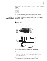
As shown in Figure 24, the PathBuilder S700 features three alarm connectors on
the rear of the unit:
n
External alarm
—Connect up to three external alarms from outside
equipment.
n
Visual alarm
—Connect a visual alarm that will illuminate whenever a critical,
major, or minor alarm occurs on the shelf. To extinguish the visual alarm, you
must clear the alarm.
n
Audible alarm
—Connect an audible alarm that will ring whenever a critical,
major, or minor alarm occurs on the shelf. To extinguish the audible alarm,
clear the alarm or press the ACO button on the front of the MCPU module.
PathBuilder S700
Power
Up
1.
2.
Power On
Tests
Completed
Power
Inservice
Fail
Test
Active
Critical
Major
ACO
Slot 1
Slot 18
Minor
CPU
LEDs
Common
System
ACO
Button
Summary of Contents for 3C63400-3AC-C - PathBuilder S700 Switch
Page 14: ...xiv CHAPTER SUPPLEMENTARY REGULATORY INFORMATION ...
Page 18: ...4 ABOUT THIS GUIDE ...
Page 28: ...14 CHAPTER 1 SYSTEM DESCRIPTION ...
Page 88: ...74 CHAPTER 3 GETTING STARTED ...
Page 260: ...246 CHAPTER 6 PATHBUILDER S700 DIAGNOSTICS AND PERFORMANCE MONITORING ...
Page 270: ...256 INDEX ...


