Step 3: (If needed) Install Additional Modules in the Shelf
21
Step 3: (If needed)
Install Additional
Modules in the Shelf
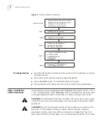
The PathBuilder S700 ships with the factory-ordered modules installed. If you have
ordered additional modules, install them as described in this section; otherwise,
proceed to “Step 4: Connect I/O Cabling and Wiring” for instructions on how to
connect the factory-installed modules and verify front panel indicators.
n
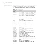
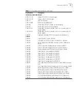
Install the Management CPU module in slot 1. (Slot 2 is reserved for a
redundant MCPU, which will be supported in subsequent releases.)
n
Install the STX module in slot 3. (Slot 4 is reserved for a redundant STX module,
which will be supported in subsequent releases.)
n
Install any one of the following application modules in slot 5-18:
n
DS3 UNI
n
E3 UNI
n
OC3/STM-1 UNI
n
DS1 UNI with IMA
n
E1 UNI with IMA
n
Ethernet
n
DSX-1 CBR
n
E1 CBR
n
QSIM (Quad Serial Interface Module)
n
HSIM (HSSI Module)
n
FAM (Frame Access Module)
To minimize reconfiguration of modules to implement future redundancy
capabilities, we recommend that you group similar modules in slots 7-11 or 12-16
and that you configure slots 17 and 18 last.
We recommend that you install OC3/STM-1 modules in slots 5 and 6 in order to
utilize their full bandwidth. Slots 5 and 6 provide 155 Mbps bandwidth for each
slot, while slots 7-18 share bandwidth (200 full-duplex Mbps for each group of
three slots: 7-9, 10-12, 13-15, and 16-18).
Slots 5 and 6 do not support rear redundant T1/E1 modules.
Summary of Contents for 3C63400-3AC-C - PathBuilder S700 Switch
Page 14: ...xiv CHAPTER SUPPLEMENTARY REGULATORY INFORMATION ...
Page 18: ...4 ABOUT THIS GUIDE ...
Page 28: ...14 CHAPTER 1 SYSTEM DESCRIPTION ...
Page 88: ...74 CHAPTER 3 GETTING STARTED ...
Page 260: ...246 CHAPTER 6 PATHBUILDER S700 DIAGNOSTICS AND PERFORMANCE MONITORING ...
Page 270: ...256 INDEX ...


