


Step 4: Connect I/O Cabling and Wiring
29
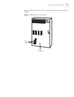
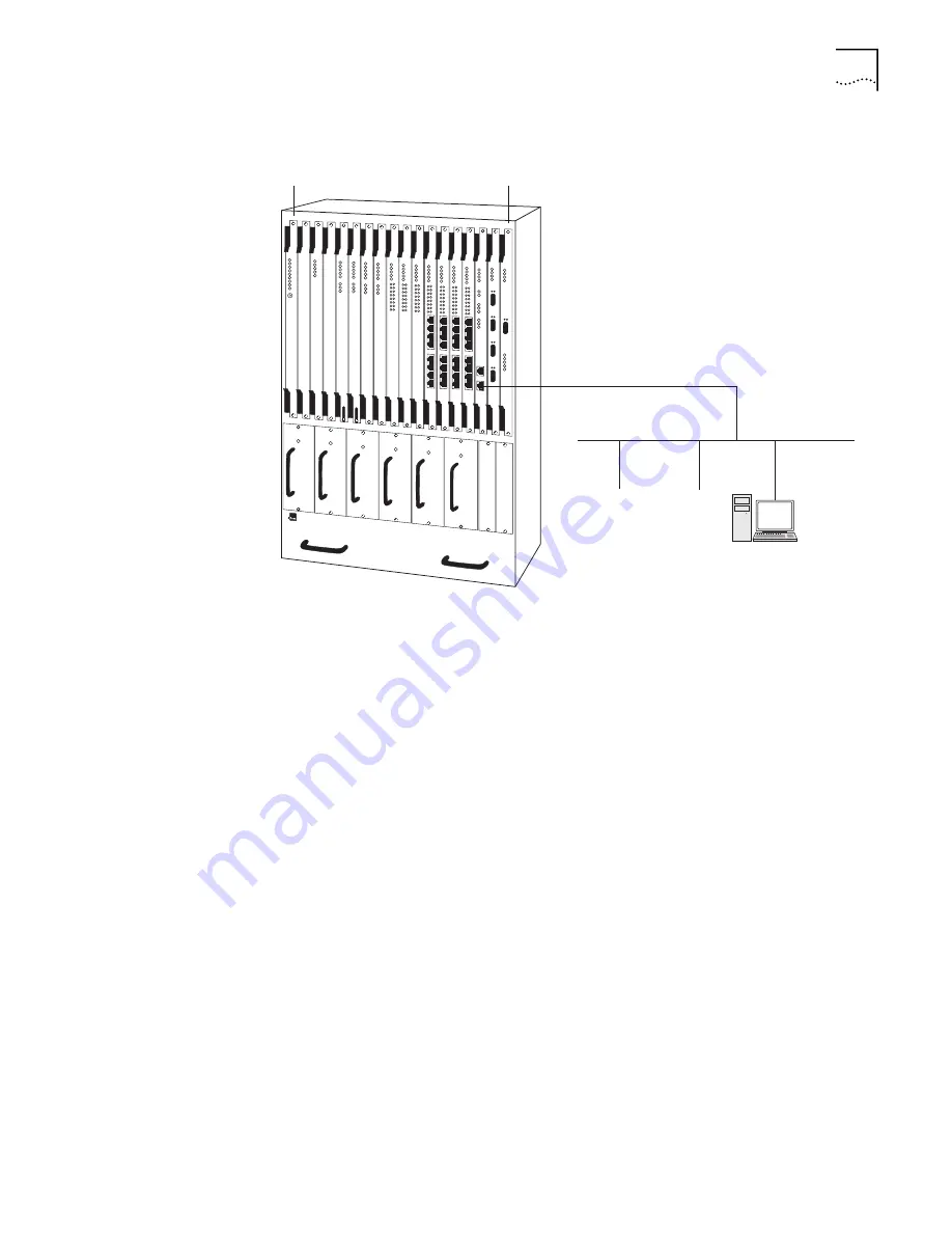
Figure 13
Ethernet Module Connection
Once you have connected the module, verify the front panel indicator sequence.
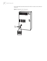
As shown in Figure 14, the Ethernet module has the following front panel
indicators in addition to the common system LEDs.
TX Port 1 (GREEN)
—This is a transmit (to the cable) activity indicator. For each
frame sent to the cable, the LED is momentarily flashed.
RX Port 1 (GREEN)
—This is a Receive (from the cable) activity indicator. For each
frame received from the cable, the LED will momentarily flash.
Link Port1 (GREEN)
—This LED will illuminate when properly connected to the
Ethernet cable, otherwise it will be off.
TX Port 2 (GREEN)
—This is a transmit (to the cable) activity indicator. For each
frame sent to the cable, the LED is momentarily flashed.
RX Port2 (GREEN)
—This is a Receive (from the cable) activity indicator. For each
frame received from the cable, the LED will momentarily flash.
Link Port 2 (GREEN)
—This LED will illuminate when properly connected to the
Ethernet cable, otherwise it will be off.
FWD (GREEN)
—This is a bridging activity detector. For each frame bridged the
LED will momentarily flash.
ATM (GREEN)
—This is an ATM traffic indicator. It illuminates when an ATM cell is
received or transmitted.
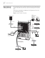
PathBuilder S700
Slot 1
Slot 18
LAN
Summary of Contents for 3C63400-3AC-C - PathBuilder S700 Switch
Page 14: ...xiv CHAPTER SUPPLEMENTARY REGULATORY INFORMATION ...
Page 18: ...4 ABOUT THIS GUIDE ...
Page 28: ...14 CHAPTER 1 SYSTEM DESCRIPTION ...
Page 88: ...74 CHAPTER 3 GETTING STARTED ...
Page 260: ...246 CHAPTER 6 PATHBUILDER S700 DIAGNOSTICS AND PERFORMANCE MONITORING ...
Page 270: ...256 INDEX ...