Configuring OSPF
429
Specifying the Router
Priority
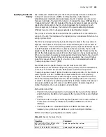
It is necessary to establish the peer relationship manually between interfaces for
multi-point access network, (NBMA and broadcast type networks). But
establishing peer relationshipoccupies large amounts of system resources when
there are hundreds of routers in the network. To resolve this issue, OSPF specifies a
“designated router” (DR). All routers within the same network segment send the
relationship information to the DR, which broadcasts the link status of each
network segment. In this way, the number of the peer relationships between
different routers on the multi-access network is significantly reduced.
The priority of a router interface determines the qualifications of the interface in
voting for the DR. The interface with a higher priority is considered first when the
voting rights conflict.
The DR is not designated manually, but voted by all routers in the local network
segment. The routers of Priority>0 in the local network segment can be used as
the “candidates”. The router with the greatest priority value is selected among all
routers that claim to be DR. If two routers have the same priority, the one with
greater router ID is selected. Routers vote by Hello packet. Each router writes the
DR into the Hello packet and sends it to all other routers on the network segment.
When two routers in the same network segment claim to be the DR, the one with
the higher priority is chosen. If the priorities are equivalent, the one with higher
router ID is chosen. If the priority of a router is 0, it is not selected as the DR or
“backup designated router” (BDR).
If a DR fails due to a specific fault, a new DR must be elected, with
synchronization. This can take a long time, during which, the route calculation is
not correct. To shorten the process, OSPF puts forward the concept of the
“backup designated router” (BDR). The BDR is actually a standby for the DR and is
voted together with DR. The BDR also creates relations with all neighboring
routers in the network segment and exchanges routing information with them.
When the DR fails, the BDR becomes the DR immediately without the need for
re-election. Because the neighboring relationship is already created, this takeover
process is instantaneous. Of course a new BDR needs to be elected again but
during the election, the route calculation is not affected.
It should be noted that:
■
The DR in the network segment is not necessarily the router with the highest
priority. Similarly, the BDR is not necessarily the router with the second highest
priority.
■
The DR is a role in a single network segment, based on the router interface. A
router can be a DR on one interface and a BDR or DROther on another
interface.
■
The DR is elected on a broadcast interface or NBMA interface. It is not
necessary on a point-to-point interface or point-to-multipoint interface.
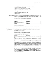
Perform the following configurations in interface view.
Table 493
Specify the Router Priority
Operation
Command
Set the priority of the interface when
selecting a designated router
ospf dr-priority
value
Return to the default router priority
undo ospf dr-priority
Summary of Contents for 3036
Page 1: ...http www 3com com 3Com Router Configuration Guide Published March 2004 Part No 10014299 ...
Page 4: ...VPN 615 RELIABILITY 665 QOS 681 DIAL UP 721 ...
Page 6: ...2 ABOUT THIS GUIDE ...
Page 7: ...I GETTING STARTED Chapter 1 3Com Router Introduction Chapter 2 3Com Router User Interface ...
Page 8: ...4 ...
Page 16: ...12 CHAPTER 1 3COM ROUTER INTRODUCTION ...
Page 34: ...30 ...
Page 60: ...56 CHAPTER 3 SYSTEM MANAGEMENT ...
Page 98: ...94 CHAPTER 6 DISPLAY AND DEBUGGING TOOLS ...
Page 110: ...106 ...
Page 114: ...110 CHAPTER 8 INTERFACE CONFIGURATION OVERVIEW ...
Page 158: ...154 CHAPTER 10 CONFIGURING WAN INTERFACE ...
Page 168: ...164 ...
Page 188: ...184 CHAPTER 13 CONFIGURING PPPOE CLIENT ...
Page 192: ...188 CHAPTER 14 CONFIGURING SLIP Router ip route static 0 0 0 0 0 0 0 0 10 110 0 1 ...
Page 248: ...244 CHAPTER 16 CONFIGURING LAPB AND X 25 ...
Page 320: ...316 ...
Page 330: ...326 CHAPTER 20 CONFIGURING IP ADDRESS ...
Page 362: ...358 CHAPTER 21 CONFIGURING IP APPLICATION ...
Page 374: ...370 CHAPTER 23 CONFIGURING IP COUNT ...
Page 406: ...402 CHAPTER 25 CONFIGURING DLSW ...
Page 408: ...404 ...
Page 452: ...448 CHAPTER 29 CONFIGURING OSPF ...
Page 482: ...478 CHAPTER 30 CONFIGURING BGP ...
Page 494: ...490 CHAPTER 31 CONFIGURING IP ROUTING POLICY ...
Page 502: ...498 ...
Page 508: ...504 CHAPTER 33 IP MULTICAST ...
Page 514: ...510 CHAPTER 34 CONFIGURING IGMP ...
Page 526: ...522 CHAPTER 36 CONFIGURING PIM SM ...
Page 528: ...524 ...
Page 532: ...528 CHAPTER 37 CONFIGURING TERMINAL ACCESS SECURITY ...
Page 550: ...546 CHAPTER 38 CONFIGURING AAA AND RADIUS PROTOCOL ...
Page 590: ...586 CHAPTER 40 CONFIGURING IPSEC ...
Page 599: ...IX VPN Chapter 42 Configuring VPN Chapter 43 Configuring L2TP Chapter 44 Configuring GRE ...
Page 600: ...596 ...
Page 638: ...634 CHAPTER 43 CONFIGURING L2TP ...
Page 649: ...X RELIABILITY Chapter 45 Configuring a Standby Center Chapter 46 Configuring VRRP ...
Page 650: ...646 ...
Page 666: ...662 ...
Page 670: ...666 CHAPTER 47 QOS OVERVIEW ...
Page 700: ...696 CHAPTER 49 CONGESTION MANAGEMENT ...
Page 706: ...702 CHAPTER 50 CONGESTION AVOIDANCE ...
Page 707: ...XII DIAL UP Chapter 51 Configuring DCC Chapter 52 Configuring Modem ...
Page 708: ...704 ...
Page 762: ...758 CHAPTER 52 CONFIGURING MODEM ...

