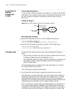
Troubleshooting
115
the party with 100 Mbps configuration shows no connection, while the party with
10 Mbps connection shows the connection has been established. Furthermore,
the activity indicator of the physical layer blink quickly and messages can not be
received or transmitted normally.
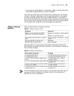
On checking the connection of fast Ethernet interface of the 3Com Router
series,
the following prompt information is very helpful. Both these two pieces of
information are output on the control console when the user is executing the rate
selection command or connecting the network cable.
Ethernet 0: Warning--the link partner do not support 100M mode
Ethernet 0: Warning--the link partner may not support 10M mode
Here, the first piece of prompt information indicates that the opposite end, which
is detected by the Ethernet interface of the 3Com Router series, does not support
100 Mbps working rate, while the local end is working at 100 Mbps rate by force.
At this time, the user should ensure that the opposite side has been configured
correspondingly and is working at the rate of 100 Mbps. The second prompt
information indicates that the opposite end, detected by the Ethernet interface of
the 3Com Router series, may not support 10 Mbps working rate, while the local
end is forced to work in 10 Mbps rate. Now, the user should ensure the opposite
end to work at the rate of 10 Mbps. However, when the Ethernet interface of the
3Com Router series is connecting 10/100 Mbps adaptive port of HUB, this
information does not mean the setting is incorrect.
2
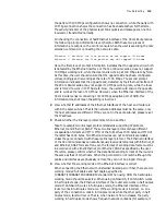
View whether IP addresses of the Ethernet interfaces of the host and router are
within the same sub-net. That is the network addresses must be the same, only
the host addresses are different. If they are not in the same sub-net, please re-set
the IP address.
3
Check whether the link layer protocols match one another.
Take for example two link layer protocol standards supporting IP protocol,
Ethernet_II and Ethernet_SNAP: These two link layer protocols have different
encapsulation formats and MTU. MTU of the former has 1500 bytes and MTU of
the latter has 1492 bytes. Two Ethernet devices can not communicate reliably
unless they are connected with the same link layer protocol. The Ethernet interface
of the 3Com Router series can simultaneously receive data frames with Ethernet_II
and Ethernet_SNAP formats. However, the format of sending data frame must be
in accordance with either Ethernet_II or Ethernet_SNAP as specified by the user.
Therefore, please confirm whether the data frame sending format of the router is
the same as that of other hosts. When the protocols do not match although the
cables and interfaces are physically normal, they can not be pinged through.
4
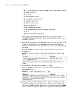
View whether the working mode of the Ethernet interface is correct.
When connecting the Ethernet with unshielded twisted pair or fiber, there are two
working modes: full duplex and half duplex, specified in
10BASE-T/100BASE-TX/100BASE-FX standard. When using HUB, the half-duplex
working mode should be selected. When using LAN Switch, if LAN Switch works
in half duplex mode, the Ethernet interface of the router also works in half duplex
mode. If LAN Switch works in full duplex mode, the Ethernet interface of the
router works in full duplex mode too. If the working mode is incorrect, i.e. one
party of the connection works in full duplex mode while the other party in half
duplex mode, fault will occur. That is, when network flow increases, the party
working in half duplex mode shows frequent network collisions (for example, if
Summary of Contents for 3036
Page 1: ...http www 3com com 3Com Router Configuration Guide Published March 2004 Part No 10014299 ...
Page 4: ...VPN 615 RELIABILITY 665 QOS 681 DIAL UP 721 ...
Page 6: ...2 ABOUT THIS GUIDE ...
Page 7: ...I GETTING STARTED Chapter 1 3Com Router Introduction Chapter 2 3Com Router User Interface ...
Page 8: ...4 ...
Page 16: ...12 CHAPTER 1 3COM ROUTER INTRODUCTION ...
Page 34: ...30 ...
Page 60: ...56 CHAPTER 3 SYSTEM MANAGEMENT ...
Page 98: ...94 CHAPTER 6 DISPLAY AND DEBUGGING TOOLS ...
Page 110: ...106 ...
Page 114: ...110 CHAPTER 8 INTERFACE CONFIGURATION OVERVIEW ...
Page 158: ...154 CHAPTER 10 CONFIGURING WAN INTERFACE ...
Page 168: ...164 ...
Page 188: ...184 CHAPTER 13 CONFIGURING PPPOE CLIENT ...
Page 192: ...188 CHAPTER 14 CONFIGURING SLIP Router ip route static 0 0 0 0 0 0 0 0 10 110 0 1 ...
Page 248: ...244 CHAPTER 16 CONFIGURING LAPB AND X 25 ...
Page 320: ...316 ...
Page 330: ...326 CHAPTER 20 CONFIGURING IP ADDRESS ...
Page 362: ...358 CHAPTER 21 CONFIGURING IP APPLICATION ...
Page 374: ...370 CHAPTER 23 CONFIGURING IP COUNT ...
Page 406: ...402 CHAPTER 25 CONFIGURING DLSW ...
Page 408: ...404 ...
Page 452: ...448 CHAPTER 29 CONFIGURING OSPF ...
Page 482: ...478 CHAPTER 30 CONFIGURING BGP ...
Page 494: ...490 CHAPTER 31 CONFIGURING IP ROUTING POLICY ...
Page 502: ...498 ...
Page 508: ...504 CHAPTER 33 IP MULTICAST ...
Page 514: ...510 CHAPTER 34 CONFIGURING IGMP ...
Page 526: ...522 CHAPTER 36 CONFIGURING PIM SM ...
Page 528: ...524 ...
Page 532: ...528 CHAPTER 37 CONFIGURING TERMINAL ACCESS SECURITY ...
Page 550: ...546 CHAPTER 38 CONFIGURING AAA AND RADIUS PROTOCOL ...
Page 590: ...586 CHAPTER 40 CONFIGURING IPSEC ...
Page 599: ...IX VPN Chapter 42 Configuring VPN Chapter 43 Configuring L2TP Chapter 44 Configuring GRE ...
Page 600: ...596 ...
Page 638: ...634 CHAPTER 43 CONFIGURING L2TP ...
Page 649: ...X RELIABILITY Chapter 45 Configuring a Standby Center Chapter 46 Configuring VRRP ...
Page 650: ...646 ...
Page 666: ...662 ...
Page 670: ...666 CHAPTER 47 QOS OVERVIEW ...
Page 700: ...696 CHAPTER 49 CONGESTION MANAGEMENT ...
Page 706: ...702 CHAPTER 50 CONGESTION AVOIDANCE ...
Page 707: ...XII DIAL UP Chapter 51 Configuring DCC Chapter 52 Configuring Modem ...
Page 708: ...704 ...
Page 762: ...758 CHAPTER 52 CONFIGURING MODEM ...

