Configure Frame Relay
249
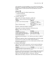
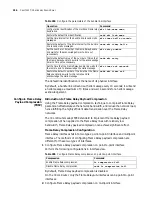
The following table describes the value ranges and default values of related
parameters of the Frame Relay LMI protocol
Table 278
D
escriptions of related parameters of Frame Relay LMI protocol
In which, the related parameters at the DTE side include:
■
T391DTE: The interval of the link integrity polling for the equipment at the DTE
side
■
N391DTE: DTE equipment will send a status enquiry message at a certain
interval (which is determined by T391). The status enquiry messages are divided
into two types: link integrity authentication messages and link status enquiry
messages. The parameter N391DTE is used to define the sending ratio of these
two types of messages. That is:
Number of link integrity authentication messages: Number of link status enquiry
messages = N391-1: 1
■
N392DTE: The threshold for the errors that can occur in the total number of
observed events at the DTE side.
■
N393DTE: The total number of observed events at the DTE side.
DTE equipment will send a status enquiry message at a certain interval (which is
determined by T391) to inquire the link status. Upon receiving that message, the
DCE equipment sends the status response message promptly. If the DTE
equipment does not receive the response in the specified time, the error will be
recorded. If the number of errors exceeds the threshold, the DTE equipment will
regard the physical path and all the virtual circuits as unusable. The parameters
N392 and N393 together define the “error threshold”. That is, if the number of
errors in the N393 status enquiry messages sent by the DTE equipment reaches
Restore the default value of the LMI event
counter
undo fr lmi n393dce
Set the link integrity polling timer at the user side
(T391 DTE)
fr lmi t391dte [
t391-value
]
Restore the default value of the link integrity
polling timer at the user side
undo fr lmi t391dte
Set the polling timer at the network side (T392
DCE)
fr lmi t392dce [
t392-value
]
Restore the default value of the polling timer at
the network side
undo fr lmi t392dce
Operation
mode
Parameter description
Value range
Default value
DTE
Link integrity polling timer (T391)
When T391 = 0, it indicates that the
LMI protocol is disabled.
5 to 30 seconds
10 seconds
Counter on the PVC full status
message polling requests (N391)
1 to 255 times
6 times
Error threshold counter at the user
side (N392)
1 to 10 times
3 times
Event counter at the user side (N393) 1 to 10 times
4 times
DCE
Polling authentication timer at the
network side (T392)
5 to 30 seconds
15 seconds
Error threshold counter at the
network side (N392)
1 to 10 times
3 times
Event counter at the network side
(N393)
1 to 10 times
4 times
Summary of Contents for 3036
Page 1: ...http www 3com com 3Com Router Configuration Guide Published March 2004 Part No 10014299 ...
Page 4: ...VPN 615 RELIABILITY 665 QOS 681 DIAL UP 721 ...
Page 6: ...2 ABOUT THIS GUIDE ...
Page 7: ...I GETTING STARTED Chapter 1 3Com Router Introduction Chapter 2 3Com Router User Interface ...
Page 8: ...4 ...
Page 16: ...12 CHAPTER 1 3COM ROUTER INTRODUCTION ...
Page 34: ...30 ...
Page 60: ...56 CHAPTER 3 SYSTEM MANAGEMENT ...
Page 98: ...94 CHAPTER 6 DISPLAY AND DEBUGGING TOOLS ...
Page 110: ...106 ...
Page 114: ...110 CHAPTER 8 INTERFACE CONFIGURATION OVERVIEW ...
Page 158: ...154 CHAPTER 10 CONFIGURING WAN INTERFACE ...
Page 168: ...164 ...
Page 188: ...184 CHAPTER 13 CONFIGURING PPPOE CLIENT ...
Page 192: ...188 CHAPTER 14 CONFIGURING SLIP Router ip route static 0 0 0 0 0 0 0 0 10 110 0 1 ...
Page 248: ...244 CHAPTER 16 CONFIGURING LAPB AND X 25 ...
Page 320: ...316 ...
Page 330: ...326 CHAPTER 20 CONFIGURING IP ADDRESS ...
Page 362: ...358 CHAPTER 21 CONFIGURING IP APPLICATION ...
Page 374: ...370 CHAPTER 23 CONFIGURING IP COUNT ...
Page 406: ...402 CHAPTER 25 CONFIGURING DLSW ...
Page 408: ...404 ...
Page 452: ...448 CHAPTER 29 CONFIGURING OSPF ...
Page 482: ...478 CHAPTER 30 CONFIGURING BGP ...
Page 494: ...490 CHAPTER 31 CONFIGURING IP ROUTING POLICY ...
Page 502: ...498 ...
Page 508: ...504 CHAPTER 33 IP MULTICAST ...
Page 514: ...510 CHAPTER 34 CONFIGURING IGMP ...
Page 526: ...522 CHAPTER 36 CONFIGURING PIM SM ...
Page 528: ...524 ...
Page 532: ...528 CHAPTER 37 CONFIGURING TERMINAL ACCESS SECURITY ...
Page 550: ...546 CHAPTER 38 CONFIGURING AAA AND RADIUS PROTOCOL ...
Page 590: ...586 CHAPTER 40 CONFIGURING IPSEC ...
Page 599: ...IX VPN Chapter 42 Configuring VPN Chapter 43 Configuring L2TP Chapter 44 Configuring GRE ...
Page 600: ...596 ...
Page 638: ...634 CHAPTER 43 CONFIGURING L2TP ...
Page 649: ...X RELIABILITY Chapter 45 Configuring a Standby Center Chapter 46 Configuring VRRP ...
Page 650: ...646 ...
Page 666: ...662 ...
Page 670: ...666 CHAPTER 47 QOS OVERVIEW ...
Page 700: ...696 CHAPTER 49 CONGESTION MANAGEMENT ...
Page 706: ...702 CHAPTER 50 CONGESTION AVOIDANCE ...
Page 707: ...XII DIAL UP Chapter 51 Configuring DCC Chapter 52 Configuring Modem ...
Page 708: ...704 ...
Page 762: ...758 CHAPTER 52 CONFIGURING MODEM ...


