114
C
HAPTER
9: C
ONFIGURING
LAN I
NTERFACE
Typical Ethernet
Interface
Configuration
Example
I. Networking Requirement
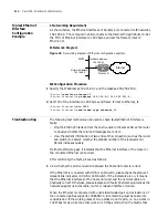
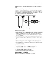
As shown below, the Ethernet interfaces of Routers A is connected to IP networks
192.168.0.0. The computer in LAN connects to the Internet through Router A. Set
the MTU of Ethernet interface to 1492 bytes, and set the frame format to
Ethernet_II.
II. Network Diagram
Figure 45
Networking diagram of Ethernet configuration example
III. Configuration Procedure
1
Specify the IP address as 192.168.0.1 and the mask as 255.255.255.0.
[Router]
interface ethernet 0
[Router-Ethernet0]
ip address 192.168.0.1 255.255.255.0
2
Set MTU of the interface to 1492 bytes and frame format to Ethernet_II.
[Router-Ethernet0]
mtu 1492
[Router-Ethernet0]
send-frame-type ethernet_ii
Troubleshooting
The following test methods can be used to check faulty Ethernet interface is
faulty:
■
Ping the Ethernet interface from the host located in the same LAN as the router
to observe whether the returned messages are correct.
■
View the statistic information of two ends of the connection (such as the router
and switch) to observe whether the statistic number of the received error
frames increases quickly.
If either test fails to pass, it indicates that the Ethernet interface of the router or
the connected Ethernet is abnormal.
After confirming the fault, proceed as follows:
1
View whether the LAN connection between the host and router is correct.
If the Ethernet is connected with HUB or LAN Switch, please check the status of
relevant link indicators on HUB or LAN Switch. If the indicators are on, it means
that the Ethernet interfaces of the host and router and the network cable are
physically correct. Otherwise, please replace such faulty physical equipment as the
network adapter, network cable, router or relevant interface module.
When the Ethernet is connected with unshielded twisted pair and at least one of
the connected parties supports 100BASE-TX, rate matching must be taken into
consideration. If the working rates of two parties do not match, i.e. one works in
100 Mbps mode while the other works in 10 Mbps mode, then the fault is that
Internet
Interface Address
192.168.0.1
E0
LAN
Router A
Network Address
192.168.0.0
Summary of Contents for 3036
Page 1: ...http www 3com com 3Com Router Configuration Guide Published March 2004 Part No 10014299 ...
Page 4: ...VPN 615 RELIABILITY 665 QOS 681 DIAL UP 721 ...
Page 6: ...2 ABOUT THIS GUIDE ...
Page 7: ...I GETTING STARTED Chapter 1 3Com Router Introduction Chapter 2 3Com Router User Interface ...
Page 8: ...4 ...
Page 16: ...12 CHAPTER 1 3COM ROUTER INTRODUCTION ...
Page 34: ...30 ...
Page 60: ...56 CHAPTER 3 SYSTEM MANAGEMENT ...
Page 98: ...94 CHAPTER 6 DISPLAY AND DEBUGGING TOOLS ...
Page 110: ...106 ...
Page 114: ...110 CHAPTER 8 INTERFACE CONFIGURATION OVERVIEW ...
Page 158: ...154 CHAPTER 10 CONFIGURING WAN INTERFACE ...
Page 168: ...164 ...
Page 188: ...184 CHAPTER 13 CONFIGURING PPPOE CLIENT ...
Page 192: ...188 CHAPTER 14 CONFIGURING SLIP Router ip route static 0 0 0 0 0 0 0 0 10 110 0 1 ...
Page 248: ...244 CHAPTER 16 CONFIGURING LAPB AND X 25 ...
Page 320: ...316 ...
Page 330: ...326 CHAPTER 20 CONFIGURING IP ADDRESS ...
Page 362: ...358 CHAPTER 21 CONFIGURING IP APPLICATION ...
Page 374: ...370 CHAPTER 23 CONFIGURING IP COUNT ...
Page 406: ...402 CHAPTER 25 CONFIGURING DLSW ...
Page 408: ...404 ...
Page 452: ...448 CHAPTER 29 CONFIGURING OSPF ...
Page 482: ...478 CHAPTER 30 CONFIGURING BGP ...
Page 494: ...490 CHAPTER 31 CONFIGURING IP ROUTING POLICY ...
Page 502: ...498 ...
Page 508: ...504 CHAPTER 33 IP MULTICAST ...
Page 514: ...510 CHAPTER 34 CONFIGURING IGMP ...
Page 526: ...522 CHAPTER 36 CONFIGURING PIM SM ...
Page 528: ...524 ...
Page 532: ...528 CHAPTER 37 CONFIGURING TERMINAL ACCESS SECURITY ...
Page 550: ...546 CHAPTER 38 CONFIGURING AAA AND RADIUS PROTOCOL ...
Page 590: ...586 CHAPTER 40 CONFIGURING IPSEC ...
Page 599: ...IX VPN Chapter 42 Configuring VPN Chapter 43 Configuring L2TP Chapter 44 Configuring GRE ...
Page 600: ...596 ...
Page 638: ...634 CHAPTER 43 CONFIGURING L2TP ...
Page 649: ...X RELIABILITY Chapter 45 Configuring a Standby Center Chapter 46 Configuring VRRP ...
Page 650: ...646 ...
Page 666: ...662 ...
Page 670: ...666 CHAPTER 47 QOS OVERVIEW ...
Page 700: ...696 CHAPTER 49 CONGESTION MANAGEMENT ...
Page 706: ...702 CHAPTER 50 CONGESTION AVOIDANCE ...
Page 707: ...XII DIAL UP Chapter 51 Configuring DCC Chapter 52 Configuring Modem ...
Page 708: ...704 ...
Page 762: ...758 CHAPTER 52 CONFIGURING MODEM ...


