Operating Principle of the Congestion Management Policies
685
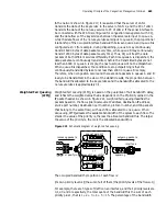
In the network shown in Figure 217, it is assumed that the server of LAN 1
transmits the data of the key service to the server of LAN 2, and the PC of LAN 1
transmits the data of the non-key service to PC of LAN 2. If the serial interface to
be connected with the WAN is configured for congestion management with CQ,
and the data flows of the key services between the servers are input to queue A,
while the data flows of the non-key services are input to queue B, the proportional
relationship of the occupied interface bandwidth between queue A and queue B is
configured as 3:1 (for example, during dispatching, queue A may continuously
transmit 6000 bytes of data packets every time, while queue B may continuously
transmit 2000 bytes of data packets every time). Thus, CQ will treat the data
packets of both different services differently. Each time queue A is dispatched, the
data packets are continuously transmitted, before the transmitted bytes are not
less than 6000 or queue A is empty, the next user queue will not be dispatched.
When queue B is dispatched, the condition to stop dispatching is that the
continuously transmitted bytes are not less than 2000 or queue B is empty.
Therefore, when congestion occurs and there are data packets in queues A and B
ready to be transmitted, in the view of the statistic results, the proportion between
the bandwidths allocated to the key services and the bandwidths allocated to the
non-key services is approximately 3:1.
Weighted Fair Queuing
(WFQ)
Weighted fair queuing (WFQ), is based on the guarantee of fair bandwidth delay,
and reflects the weighted value that is dependent on the PI priority carried in the
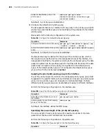
IP packet header. As shown in Figure 221, weighted fair queuing classifies the
packets based on the flows (identical source IP address, destination IP address,
source port number, destination port number, protocol number, and ToS packets
that belong to the same flow), with each flow allocated to one queue. When
dequeuing, WFQ allocates the available bandwidth of the egress to each flow. The
smaller the value of the priority is, the less the allocated bandwidth is. The larger
the value of the priority is, the more the allocated bandwidth is.
Figure 221
Schematic diagram of weighted fair queuing
The occupied bandwidth proportion of each flow is:
(its own priority level+1)/(the sum of all of them (the priority levels of the flows+1))
For example, there are 5 types of traffic on an interface, and their priority levels are
0,1,2,3 and 4 respectively, the total quota of the bandwidth is the sum of each
priority plus 1, that is 1 + 2 + 3 + 4 + 5 = 15. The percentage of the bandwidth
i ncomi ng packet s
queue1 wei ght 1
queue2 wei ght 2
cl assi f yi ng
out goi ng packet s
queueN- 1 wei ght N- 1
queueN wei ght N
queuei ng
i nt er f ace
¡- ¡-
Summary of Contents for 3036
Page 1: ...http www 3com com 3Com Router Configuration Guide Published March 2004 Part No 10014299 ...
Page 4: ...VPN 615 RELIABILITY 665 QOS 681 DIAL UP 721 ...
Page 6: ...2 ABOUT THIS GUIDE ...
Page 7: ...I GETTING STARTED Chapter 1 3Com Router Introduction Chapter 2 3Com Router User Interface ...
Page 8: ...4 ...
Page 16: ...12 CHAPTER 1 3COM ROUTER INTRODUCTION ...
Page 34: ...30 ...
Page 60: ...56 CHAPTER 3 SYSTEM MANAGEMENT ...
Page 98: ...94 CHAPTER 6 DISPLAY AND DEBUGGING TOOLS ...
Page 110: ...106 ...
Page 114: ...110 CHAPTER 8 INTERFACE CONFIGURATION OVERVIEW ...
Page 158: ...154 CHAPTER 10 CONFIGURING WAN INTERFACE ...
Page 168: ...164 ...
Page 188: ...184 CHAPTER 13 CONFIGURING PPPOE CLIENT ...
Page 192: ...188 CHAPTER 14 CONFIGURING SLIP Router ip route static 0 0 0 0 0 0 0 0 10 110 0 1 ...
Page 248: ...244 CHAPTER 16 CONFIGURING LAPB AND X 25 ...
Page 320: ...316 ...
Page 330: ...326 CHAPTER 20 CONFIGURING IP ADDRESS ...
Page 362: ...358 CHAPTER 21 CONFIGURING IP APPLICATION ...
Page 374: ...370 CHAPTER 23 CONFIGURING IP COUNT ...
Page 406: ...402 CHAPTER 25 CONFIGURING DLSW ...
Page 408: ...404 ...
Page 452: ...448 CHAPTER 29 CONFIGURING OSPF ...
Page 482: ...478 CHAPTER 30 CONFIGURING BGP ...
Page 494: ...490 CHAPTER 31 CONFIGURING IP ROUTING POLICY ...
Page 502: ...498 ...
Page 508: ...504 CHAPTER 33 IP MULTICAST ...
Page 514: ...510 CHAPTER 34 CONFIGURING IGMP ...
Page 526: ...522 CHAPTER 36 CONFIGURING PIM SM ...
Page 528: ...524 ...
Page 532: ...528 CHAPTER 37 CONFIGURING TERMINAL ACCESS SECURITY ...
Page 550: ...546 CHAPTER 38 CONFIGURING AAA AND RADIUS PROTOCOL ...
Page 590: ...586 CHAPTER 40 CONFIGURING IPSEC ...
Page 599: ...IX VPN Chapter 42 Configuring VPN Chapter 43 Configuring L2TP Chapter 44 Configuring GRE ...
Page 600: ...596 ...
Page 638: ...634 CHAPTER 43 CONFIGURING L2TP ...
Page 649: ...X RELIABILITY Chapter 45 Configuring a Standby Center Chapter 46 Configuring VRRP ...
Page 650: ...646 ...
Page 666: ...662 ...
Page 670: ...666 CHAPTER 47 QOS OVERVIEW ...
Page 700: ...696 CHAPTER 49 CONGESTION MANAGEMENT ...
Page 706: ...702 CHAPTER 50 CONGESTION AVOIDANCE ...
Page 707: ...XII DIAL UP Chapter 51 Configuring DCC Chapter 52 Configuring Modem ...
Page 708: ...704 ...
Page 762: ...758 CHAPTER 52 CONFIGURING MODEM ...


