


FORM 201.24-NM2
95
YORK INTERNATIONAL
NOTES (for Electrical Data on pages 92-94)
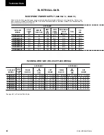
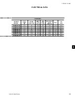
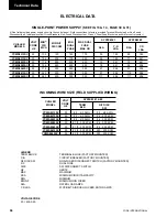
1. Minimum Circuit Ampacity (MCA) is based on 125% of the rated load amps for the largest motor plus 100%
of the rated load amps for all other loads included in the circuit, per N.E.C. Article 430-24. If the optional
Factory-mounted Control Transformer is provided, add the following MCA values to the electrical tables for
the system providing power to the transformer: -50, add 5 amps;
2. The minimum recommended disconnect switch is based on 115% of the rated load amps for all loads included
in the circuit, per N.E.C. Article 440.
3. Minimum fuse size is based upon 150% of the rated load amps for the largest motor plus 100% of the rated load
amps for all other loads included in the circuit to avoid nuisance trips at start-up due to lock rotor amps. It is not
recommended in applications where brown outs, frequent starting and stopping of the unit, and/or operation at
ambient temperatures in excess of 35°C (95°F) is anticipated.
4. Maximum fuse size is based upon 225% of the rated load amps for the largest motor plus 100% of the rated
load amps for all other loads included in the circuit, per N.E.C. Article 440-22.
5. Circuit breakers supplied by third party vendors must be certified by local electrical standards. Maximum size
is based on 225% of the rated load amps for the largest motor plus 100% of the rated load amps for all other
loads included in the circuit.
6. The “INCOMING WIRE RANGE” is the minimum and maximum wire size that can be accommodated by the
unit wiring lugs. The (2) preceding the wire range indicates the number of termination points available per
phase of the wire range specified. Actual wire size and number of wires per phase must be determined based on
the National Electrical Code, using copper connectors only. Field wiring must also comply with local codes.
7. A ground lug is provided for each compressor system to accommodate a field grounding conductor per N.E.C.
Table 250-95. A control circuit grounding lug is also supplied.
8. The supplied disconnect is a “Disconnecting Means” as defined in the N.E.C. 100, and is intended for isolating
the unit for the available power supply to perform maintenance and troubleshooting. This disconnect is not
intended to be a Load Break Device.
9. Field Wiring by others which complies to the National Electrical Code & Local Codes.
ELECTRICAL DATA NOTES
9
Содержание YCWS0313SC
Страница 12: ...YORK INTERNATIONAL 12 THIS PAGE INTENTIONALLY LEFT BLANK TO MAINTAIN PAGE FORMAT...
Страница 36: ...YORK INTERNATIONAL 36 THIS PAGE INTENTIONALLY LEFT BLANK TO MAINTAIN PAGE FORMAT Commissioning...
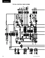
Страница 86: ...YORK INTERNATIONAL 86 TYPICAL CONTROL PANEL WIRING Maintenance...
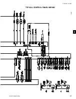
Страница 87: ...FORM 201 24 NM2 87 YORK INTERNATIONAL TYPICAL CONTROL PANEL WIRING LD06957 8...
Страница 91: ...FORM 201 24 NM2 91 YORK INTERNATIONAL THIS PAGE INTENTIONALLY LEFT BLANK TO MAINTAIN PAGE FORMAT 9...
Страница 101: ...FORM 201 24 NM2 101 YORK INTERNATIONAL SECTION 10 SPARE PARTS This information will be available at a later date 10...
Страница 103: ...FORM 201 24 NM2 103 YORK INTERNATIONAL NOTES 11...