


FORM 201.24-NM2
15
YORK INTERNATIONAL
The automatic spring return of the capacity control
valve to the minimum load position will ensure com-
pressor starting at minimum motor load.
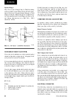
OIL SEPARATOR
Each circuit has a high efficiency, augmented gas im-
pingement type oil separator to maximize oil extrac-
tion without fragile media to break down.
The oil separator, is mounted in the discharge line of
the compressor. The high pressure discharge gas is
forced around a 90 degree bend. Oil is forced to the
outside of the separator through centrifugal action and
captured on wire mesh where it drains to the bottom of
the oil separator and into the compressor.
The oil drains back into the compressor through a re-
placeable 0.5-3.0 micron oil filter, and oil supply sole-
noid, is at high pressure. This high pressure “oil injec-
tion” forces the oil into the compressor where it is grav-
ity fed to the rotors and bearings for lubrication.
After lubricating the rotor and bearings, it is injected
through orifices on a closed thread near the suction end
of the rotors. The oil is automatically injected because
of the pressure difference between the discharge pres-
sure and the reduced pressure at the suction end of the
rotors. This lubricates the rotors as well as provides an
oil seal against leakage around the rotors to assure re-
frigerant compression (volumetric efficiency).
The oil also provides cooling by transferring much of
the heat of compression from the gas to the oil keeping
discharge temperatures down and reducing the chance
for oil breakdown.
Oil injected into the rotor cage flows into the rotors at
a point about 1.2 x suction. This assures that a required
minimum differential of at least 1.8 bar exists between
discharge and 1.2 x suction, to force oil into rotor case,
a minimum of 0.6 bar is all that is required to assure
protection of the compressor. Oil pressure is measured
as the difference between discharge pressure and the
pressure of the oil entering the rotor case.
Maximum working pressure of the oil separator is 31
bar (450 psi). A relief valve is installed in the oil sepa-
rator piping. The oil level should be above the mid-
point of the “lower” oil sight glass when the compres-
sor is running. The oil level should never be above the
top of the “upper” sight glass.
Oil temperature control is provided through liquid in-
jection activated by the microprocessor, utilizing a tem-
perature sensor, and a solenoid valve.
OIL COOLER
Compressor oil cooling is provided by refrigerant liq-
uid, which is injected into the rotor suction when the
temperature setpoint has been exceeded.
REFRIGERANT CIRCUITS
Each refrigerant circuit uses copper refrigerant pipe
formed on computer controlled bending machines to
reduce the number of brazed joints resulting in a reli-
able and leak resistant system.
Liquid line components include: a manual shut-off
valve with charging port, a high absorption removable
core filter-drier, a solenoid valve, a sight glass with
moisture indicator, and a thermostatic expansion valve.
Suction lines are covered with closed-cell insulation.
CONDENSER
The dual refrigerant circuit water-cooled condenser is
a cleanable shell and tube type with seamless external
finned 19 mm OD copper tubes rolled into tube sheets.
The design working pressures are 10 bar g on the wa-
terside and 23 bar (330 PSIG) on the refrigerant side
which is protected by pressure relief valve(s).
The condenser has removable steel water heads. The
water nozzles are provided with grooves for victualic
couplings.
COOLER
The 4 pass dual circuit shell and tube type direct ex-
pansion (DX) evaporator has chilled liquid circulating
back and forth across the tubes from one end to the
other. The design working pressures of the cooler are
10 bar (150 psi) on the waterside (shell) and 20 bar
(300 psi) on the refrigerant side (tubes) which is pro-
tected by pressure relief valve(s).
The water baffles are fabricated from galvanized steel
to resist corrosion. Removable heads are provided for
access to internally enhanced, seamless, copper tubes.
Water vent and drain connections are included. The
cooler is insulated with flexible closed-cell foam.
2
Содержание YCWS0313SC
Страница 12: ...YORK INTERNATIONAL 12 THIS PAGE INTENTIONALLY LEFT BLANK TO MAINTAIN PAGE FORMAT...
Страница 36: ...YORK INTERNATIONAL 36 THIS PAGE INTENTIONALLY LEFT BLANK TO MAINTAIN PAGE FORMAT Commissioning...
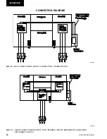
Страница 86: ...YORK INTERNATIONAL 86 TYPICAL CONTROL PANEL WIRING Maintenance...
Страница 87: ...FORM 201 24 NM2 87 YORK INTERNATIONAL TYPICAL CONTROL PANEL WIRING LD06957 8...
Страница 91: ...FORM 201 24 NM2 91 YORK INTERNATIONAL THIS PAGE INTENTIONALLY LEFT BLANK TO MAINTAIN PAGE FORMAT 9...
Страница 101: ...FORM 201 24 NM2 101 YORK INTERNATIONAL SECTION 10 SPARE PARTS This information will be available at a later date 10...
Страница 103: ...FORM 201 24 NM2 103 YORK INTERNATIONAL NOTES 11...