


YORK INTERNATIONAL
26
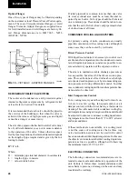
Option Flanges
One of two types of flanges may be fitted depending
on the customer or local Pressure Vessel Code require-
ments. These are Victaulic-Adapter flanges or weld
flanges. Victaulic-Adapter flanges are supplied loose
for field installation and weld flanges are factory fit-
ted. Flange dimensions are to ISO 7005 - NP10
(BS 4504 - NP10).
REFRIGERANT RELIEF VALVE PIPING
The cooler and condenser are each protected against
internal refrigerant overpressure by refrigerant relief
valves. Refer to Section 9 for details.
It is recommended that each valve should be piped to
the exterior of the building so that when the valve is
activated the release of high pressure gas and liquid
cannot be a danger or cause injury.
The size of any pipework attached to a relief valve must
be of sufficient diameter so as not to cause resistance
to the operation of the valve. Unless otherwise speci-
fied by local regulations, the internal diameter depends
on the length of pipe required and is given by the fol-
lowing formula:
D
5
= C x L
Where:
D = minimum pipe internal diameter in centimeters
L = length of pipe in meters
C = value in table below
FIG. 10 – VICTAULIC - ADAPTER FLANGES
If relief pipework is common to more than one valve
its cross sectional area must be at least the total re-
quired by each valve. Valve types should not be mixed
on a common pipe. Precautions should be taken to en-
sure that the exit of relief valves/vent pipe remain clear
of obstructions at all times.
CONDENSER COOLING LIQUID SYSTEMS
For primary cooling of units, condensers are usually
piped in conjunction with a cooling tower, although in
some cases they can be cooled by well water.
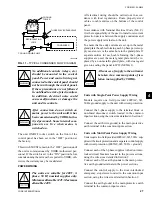
Direct Pressure Control
With liquid cooled units it is necessary to control cool-
ant flow and/or temperature into the condenser to main-
tain refrigerant pressure as constant as possible to en-
sure satisfactory operation of the expansion valves.
The aim is to maintain a stable discharge pressure as
low as possible, but at least 5.2 bar above suction pres-
sure. This can be done at a fixed value above the high-
est expected suction pressure, or by also measuring suc-
tion pressure and using differential control. In either
case condenser cooling liquid flow and temperature lim-
its must also be observed.
Inlet Temperature Control
For a cooling tower system the simplest forms of con-
trol are to use fan cycling, fan speed control, or air
damper control, with the tower having a thermostat in
its sump. This will ensure stable condenser cooling liq-
uid temperature sensing at design conditions and should
be adjusted to ensure a condenser cooling liquid enter-
ing temperature of not lower than 21°C to 24°C at lower
ambient conditions.
If these methods are not available, or a cooling tower
is not the source of cooling water, then a three way
valve recirculation system can be used with control
based on condenser inlet liquid temperature. In this case
the objective is to maintain the inlet cooling liquid tem-
perature as low as possible, although still observing
the minimum limit of 21°C to 24°C.
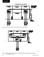
ELECTRICAL CONNECTION
The following connection recommendations are in-
tended to ensure safe and satisfactory operation of the
unit. Failure to follow these recommendations could
cause harm to persons, or damage to the unit, and may
invalidate the warranty.
Installation
LD06602
Содержание YCWS0313SC
Страница 12: ...YORK INTERNATIONAL 12 THIS PAGE INTENTIONALLY LEFT BLANK TO MAINTAIN PAGE FORMAT...
Страница 36: ...YORK INTERNATIONAL 36 THIS PAGE INTENTIONALLY LEFT BLANK TO MAINTAIN PAGE FORMAT Commissioning...
Страница 86: ...YORK INTERNATIONAL 86 TYPICAL CONTROL PANEL WIRING Maintenance...
Страница 87: ...FORM 201 24 NM2 87 YORK INTERNATIONAL TYPICAL CONTROL PANEL WIRING LD06957 8...
Страница 91: ...FORM 201 24 NM2 91 YORK INTERNATIONAL THIS PAGE INTENTIONALLY LEFT BLANK TO MAINTAIN PAGE FORMAT 9...
Страница 101: ...FORM 201 24 NM2 101 YORK INTERNATIONAL SECTION 10 SPARE PARTS This information will be available at a later date 10...
Страница 103: ...FORM 201 24 NM2 103 YORK INTERNATIONAL NOTES 11...